m330_01_gas_cabinet气柜.pdf.pdf - 第16页
GAS SYSTEM Trans-LC ® bubbler system The Trans 1,2 Dichloroethylene (Tr ans-LC ® ) is an Schumacher ozon-safe liq uid chlorine source in silicon oxidation and tube cleaning. Fo r more information about the properties and…

GAS SYSTEM
will maintain the temperature of the source chemical in the Bubbler within ±0.2
0
C of the
selected temperature.
Schumacher ATCS bubbler system include standard temperature range (POCl
3
, TMB), high
temperature range (TEOS) and TransLC specific models.
GAS CABINET REFERENCE MANUAL
2-10

GAS SYSTEM
Trans-LC
®
bubbler system
The Trans 1,2 Dichloroethylene (Trans-LC
®
) is an Schumacher ozon-safe liquid chlorine
source in silicon oxidation and tube cleaning. For more information about the properties and
applications of TransLC
®
see the process manual.
The Trans-LC bubbler system consists of the following components:
• Trans-LC System
• Source System
• Base System
• Control Unit
The ATCS-TLC is modified to fit the Trans-LC properties. The Source unit (ATCS) is
equipped with an over temperature cut-out switch in the TLC model. The temperature
setpoint is hardware limited to a range of 10
0
C to 22
0
C.
The temperature alarm window is opened from the standard +
2
0
C to + 5
0
C.
The Schumacher Smart Probe is included. This probe system prevents the Bubbler from
being installed in the incorrect orientation that may interfere with the level sensing system.
The probe system also generates a temperature alarm and prevents the heater from operating
if the temperature probe is not fully inserted through the front insulation cover hole and into
the Bubbler.
Potential spark sources are removed from both the Source Unit and Basic Unit. These units
are suitable for use in an area where Trans-LC vapors may be present. The Control Unit does
not have spark or ignition sources removed and therefore must be located in an area where
explosive vapors are not present.
WARNING: EXPLOSION HAZARD. Spark or ignition
sources are present in the Control Unit. The user must ensure that
the Control Unit is located in an area where explosive vapors are
not present. Under no circumstances should electrical connectors be
connected or disconnected while the equipment is energized.
External torches
The Tempress Standard External Torch is compromised of a water-cooled stainless steel shell,
which contains a quartz balloon (in which the steam will be produced), a mixer-assy, a ball-joint
and a heating element. It generates high purity steam, without detrimental effects on the
temperature profile of the furnace. The location of the external torch is in the gassource
cabinet. A thermocouple is inserted in the inner tube of the mixer assy. O
2
and H
2
are fed
separately into the mixer-assy and are heated above 750
0
C. When the gases are mixing in the
quartz balloon, the H
2
ignites spontaneously and water vapour is produced. The torch
temperature is regulated by a digital temperature controller. For more detailed information see
the enclosed “External Torch Manual
”.
GAS CABINET REFERENCE MANUAL
2-11
GAS SYSTEM
A Persys Pyrogenic External Torch can be used only on customers request. For more
information about the Persys Pyrogenic External Torch, refer to its user manual, see Vendor
documentation (M540.00).
Coldtrap
A coldtrap is necessary whenever a process produces condensable waste products, which can
contaminate vacuumlines and potentially cause particle problems. An example of such a
process is silicon-nitride (Si
3
N
4
) from SiH
2
Cl
2
and NH
3
.
The gasses should cool down on a cold surface so it is important to have that surface as close
to the entrance of the cold-trap as possible. A cooling water temperature of 15
o
C is required
for an optimized operation.
Specifically for the nitride deposition process two different forms of waste product can be
found in the coldtrap. A white powder form and a glassy solid form. The glassy form is what
occurs as the gasses are shock-cooled on any cold surface. This is the form that is wanted on
the coldtrap. The white powder form occurs from slow cooling and condensation in the gas-
phase, and will hardly be trapped by the coldtrap. Instead, most of it will be found at the inlet
filter and exhaust of the dry pump, or in the oil of a wet pump. A short connection between
tube and coldtrap should decrease the amount of powder form and increase the glassy form.
Special precautions are required to prevent O-ring damage or melting.
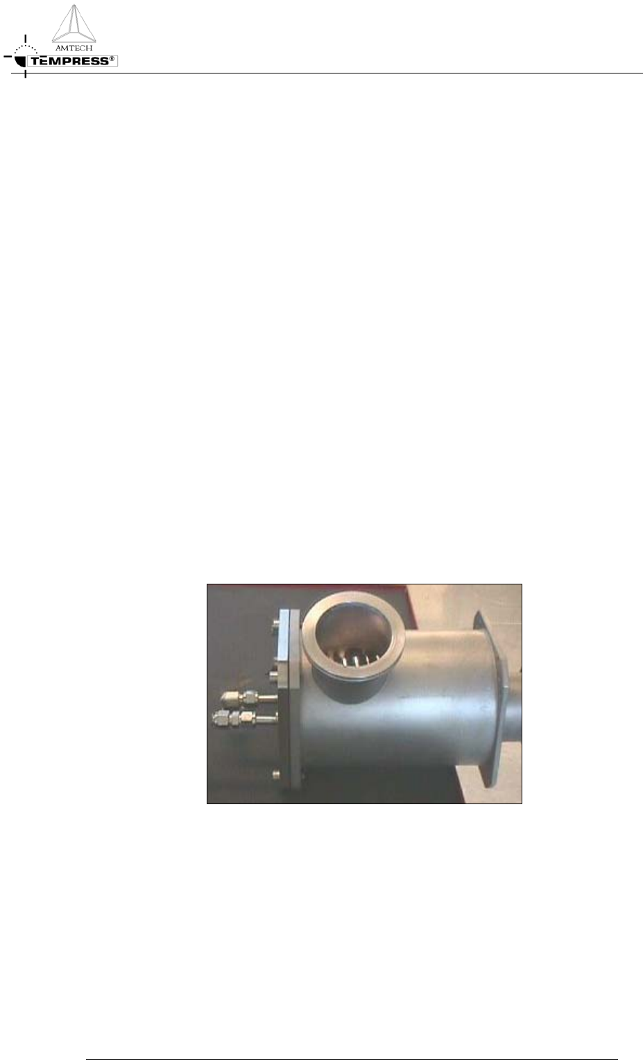
A coldtrap usually consists of two parts: the outer housing and the inner cooling element.
Waste products of the deposition process are rapidly cooled off on the inner element and
removed from the gas stream.
Figure 2-9 Coldtrap (small design)
Figure 2-10 shows a spiral tube with the incoming cooling line in the center, spiraling down
to the bottom. Some white NH
4
Cl deposit is visible which can be removed by rinsing into
hot water.
GAS CABINET REFERENCE MANUAL
2-12