00192471-03.pdf - 第135页
User Manual SIPLAC E HS-50 4 Component han dling Software Version SR.50x.xx 01/2006 US Edition 4.6 Component changeover tables 135 4.6 Component chan geover t a bles 4.6.1 Safety instruct ions for docking and undocking t…
4 Component handling User Manual SIPLACE HS-50
4.5 Used tape cutter Software Version SR.50x.xx 01/2006 US Edition
134
The used tape guide channels (see item 1 in Fig. 4.5 - 3) are located upstream of the feeder mod-
ules. They are positioned directly above the used tape cutters (see item 3 in Fig. 4.5 - 3
). 4
The tape is automatically guided through the used tape guide channel into the used tape cutter
below. There, the tape is shredded by the pneumatically-actuated cutting blade. The waste tape
then passes via the waste tape chute (see item 4 in Fig. 4.5 - 3
) into the component table’s waste
container. 4
4
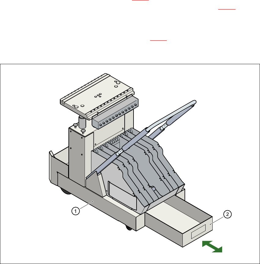
Fig. 4.5 - 4 Removable waste tape container in the component changeover table
(1) Component changeover table
(2) Removable waste tape container
4
User Manual SIPLACE HS-50 4 Component handling
Software Version SR.50x.xx 01/2006 US Edition 4.6 Component changeover tables
135
4.6 Component changeover tables
4.6.1 Safety instructions for docking and undocking the component changeover
table
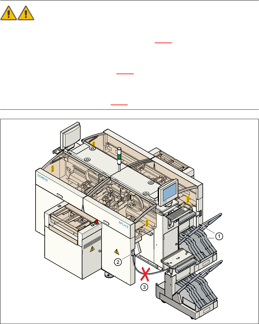
WARNING 4
Æ Never reach into the gaps between the component changeover table and the placement sys-
tem frame while the machine is running (item 1 in Fig. 4.6 - 1
).
Æ Always check that the component changeover table is docked on the placement system before
connecting or disconnecting the power cable for the component changeover table at the socket
on the placement system (item 2 in Fig. 4.6 - 1
).
Æ NEVER connect the connecting cable for the component changeover table to the socket on the
placement system and then operate the component table outside the machine via the com-
pressed air control unit (item 3 in Fig. 4.6 - 1).
4
Fig. 4.6 - 1 Safety instructions for the component changeover table
4 Component handling User Manual SIPLACE HS-50
4.6 Component changeover tables Software Version SR.50x.xx 01/2006 US Edition
136
4.6.2 Undocking the component changeover table
Æ Click on the STOP PROCESSING icon in the MAIN VIEW menu.
Æ The PCB in progress will be completed. The icons of the SINGLE FUNCTIONS menu will then
be activated.
Æ Click on the SINGLE FUNCTIONS GANTRY X icon (gantry 1, 2, 3 or 4).
Æ Click on the GANTRY FUNCTIONS icon.
Æ From this menu, click on the APPROACH SET-UP POSITION button.
Æ The selected placement head will move across the PCB transport to prevent it being damaged
when the component table is changed.
Æ Fold up the protective cover of the selected gantry.
Æ Lift up the clip (item 5) to lock the raised component table bed in its top end position.
Æ Lift the flap over the button (item 1).
Æ Hold down the button (item 1) for raising the component table bed (item 3) until the component
table bed reaches its top end position.
Æ Unplug the component changeover table (item 2) from the placement system.
Æ Remove the component changeover table.
4