00192471-03.pdf - 第171页
User Manual SIPLACE HS-50 5 Station extensions Software Version SR.50x.xx 01/2006 US Edition 5.8 Fine calibration 171 5.8 Fine calibration 5.8. 1 Ove rview Fine cali bration involves measuring t he mac hine’s placeme nt …
5 Station extensions User Manual SIPLACE HS-50
5.7 Feeder position recognition Software Version SR.50x.xx 01/2006 US Edition
170
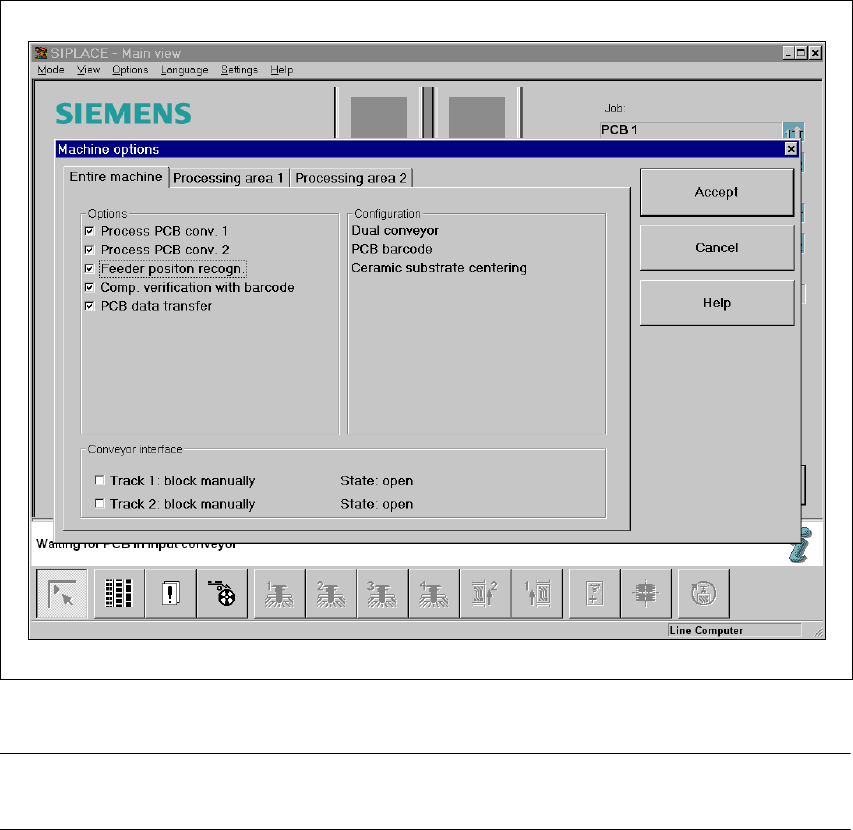
5.7 Feeder position recognition
If the feeder modules are equipped with positioning fiducials, the fiducials can be measured.
If the "Conveyor position detection" function has been selected on the line computer, the function
will also appear in the Machine options. It can then be activated or deactivated at each station.
Fig. 5.7 - 1 Feeder position recognition
PLEASE NOTE 5
The "Feeder position recognition" function is always deactivated when the station is switched on.
If a track has been entered in the cluster data, the PCB camera on the feeder module will approach
the position of the centering fiducial. Any centering fiducial offset determined during the measure-
ment will then be assigned to this track and added to the pick-up position during the pick-up op-
eration.

User Manual SIPLACE HS-50 5 Station extensions
Software Version SR.50x.xx 01/2006 US Edition 5.8 Fine calibration
171
5.8 Fine calibration
5.8.1 Overview
Fine calibration involves measuring the machine’s placement offset and determining the required
correction from this value. The ‘Fine calibration’ measuring program is integrated into the
SITEST program, and a detailed description of the measuring procedure is given in the ‘Fine
calibration’ instructions (article no. 00191655-01).
CAUTION
The SITEST program is password-protected. It must only be called up and used by Siemens
engineers or appropriately trained personnel. 5
5.8.2 System requirements
The following system requirements must be fulfilled in order to use the fine calibration program:
Machine type HS-50
Station computer software version 502.xx or later
SITEST version 502.xx or later
5.8.3 Measuring equipment and tools
The following are supplied as standard:
– Mapping plate (glass plate in a metal frame)
– Double-sided transparent adhesive film
– Lighting unit
– Magazine with 48 glass components
– Magazine with 196 ceramic components
The following items must be ordered:
– Manual tray (waffle tray holder) to hold the magazine for the glass and/or ceramic components
5 Station extensions User Manual SIPLACE HS-50
5.8 Fine calibration Software Version SR.50x.xx 01/2006 US Edition
172
The following parts may be ordered if required:
– Magazine with 48 glass components
– Magazine with 196 ceramic components
5.8.4 Functional description
First select the placement program for fine calibration by selecting the ‘Cluster for fine calibration’
option from the ‘Options’ pull-down menu. Then process the mapping plate with the glass
components from a magazine on the manual tray.
After placement, start the SITEST program and run the ‘Fine calibration’ measuring program.
The placement head (Collect&Place head or Pick&Place head) will measure the current
placement positions of the glass and/or ceramic components and compare these positions with
the circular fiducials on the mapping plate.
The 48 glass components are used to calculate the offset values in the X and Y directions and the
angular deviation.
The 196 ceramic components are used to verify and confirm the measured offset values. Ceramic
component cannot be used for angle correction.
The offset values are used to determine the corrected values, which are then entered in the
machine’s machine data.