00198353-01_AI_Location 1 Upgrade Kit_E by SIPLACE_en.pdf - 第18页
2 Installing the Location 1 Upgrade Kit [03113225‑xx] (FixedtoMov- 2.2 Installing the Location 1 Upgrade Kit Assembly Instructions E by SIPLACE Location 1 Upgrade Kit 04/2017 18 ► Install the adhesive cable tie mounts …
Assembly Instructions E by SIPLACE
Location 1 Upgrade Kit 04/2017
2 Installing the Location 1 Upgrade Kit [03113225‑xx] (FixedtoMov-
2.2 Installing the Location 1 Upgrade Kit
17
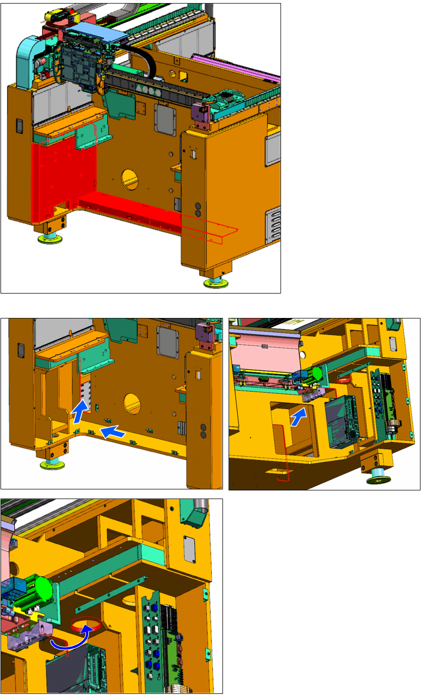
► Remove the three location 2
covers shown above. They
will be fixed back after rout-
ing the tube.
► Route the tubing mentioned before from
the Air Service Unit to location 1 as
shown.
2 Installing the Location 1 Upgrade Kit [03113225‑xx] (FixedtoMov-
2.2 Installing the Location 1 Upgrade Kit
Assembly Instructions E by SIPLACE
Location 1 Upgrade Kit 04/2017
18
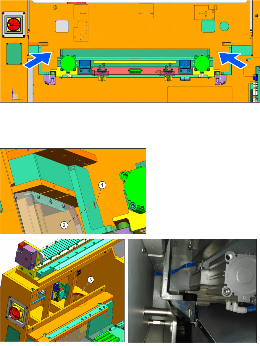
► Install the adhesive cable tie mounts at the two locations shown.
► Take the two tubes 4A_BTM-TEE_L1 [03111719-xx].
► Mark one of the two tubes at both ends of the tube. This will identify it as the tube that con-
nects to the rear port of the left cylinder.
1. Hole 1
2. Hole 2
3. Hole 3
► Stretch the two tubes from left to right behind the tape cutter.
► Use cable ties to loosely secure the tubes to the cable tie bases installed before.
► Thread the two tubes [03111719-xx] through hole 1 and hole 2 and up through hole 3.
Assembly Instructions E by SIPLACE
Location 1 Upgrade Kit 04/2017
2 Installing the Location 1 Upgrade Kit [03113225‑xx] (FixedtoMov-
2.3 Installing Table Insert Sub-Assemblys
19
2.3 Installing Table Insert Sub-Assemblys
Insert Left Sub-Assembly (w/ Fastening) [03111428-xx]
Qty Description Part Number
1 E-series Table Insert Left Sub-Assembly 03104649-xx
2 ISO 8735- 8 x 28-B-ST 03016102-xx
2 ISO 7093-1 - 6 - 200 HV - A2 03022709-xx
1 ISO 7090 - 8 - 200HV - A2 03090874-xx
2 ISO 4762 - M 6 x 30-A2-70 03042576-xx
1 ISO 4762 - M 8 x 30-A2-70 03042587-xx
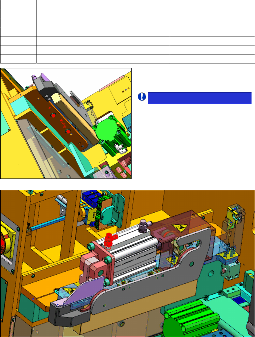
► Install the E-series table insert left sub-
assembly [03104649-xx] onto the frame
with the fasteners shown.
NOTICE!
The M6 screws and one of the
ISO8735 dowels are inserted from
below.
.
► From the steps before insert the tube [03111719-xx] with the marking into the rear port of the
cylinder.
► Insert the unmarked tube [03111719-xx] into the Tee Joint.
► Joint the Tee Joint to the front port of the cylinder with the tube [03111723-xx].
► Connect the 4mm tube from the push-out cylinder in the E-series table insert left sub-as-
sembly [03104649‑xx] to the 4mm output of the Tee Joint.