213155.pdf - 第6页
06-May-25 page 6 of 13 DQ12 Series Sensor © Banner Engineering Corp. All rights reserved. www .bannerengineering.com Chapter Contents FCC Part 15 Class A for Unintentional Radiators..................................…
06-May-25 page5of13
DQ12 Series Sensor
© Banner Engineering Corp. All rights reserved.
www.bannerengineering.com
•
•
•
Chapter Contents
Wiring ................................................................................................................................................................................................................... 5
1
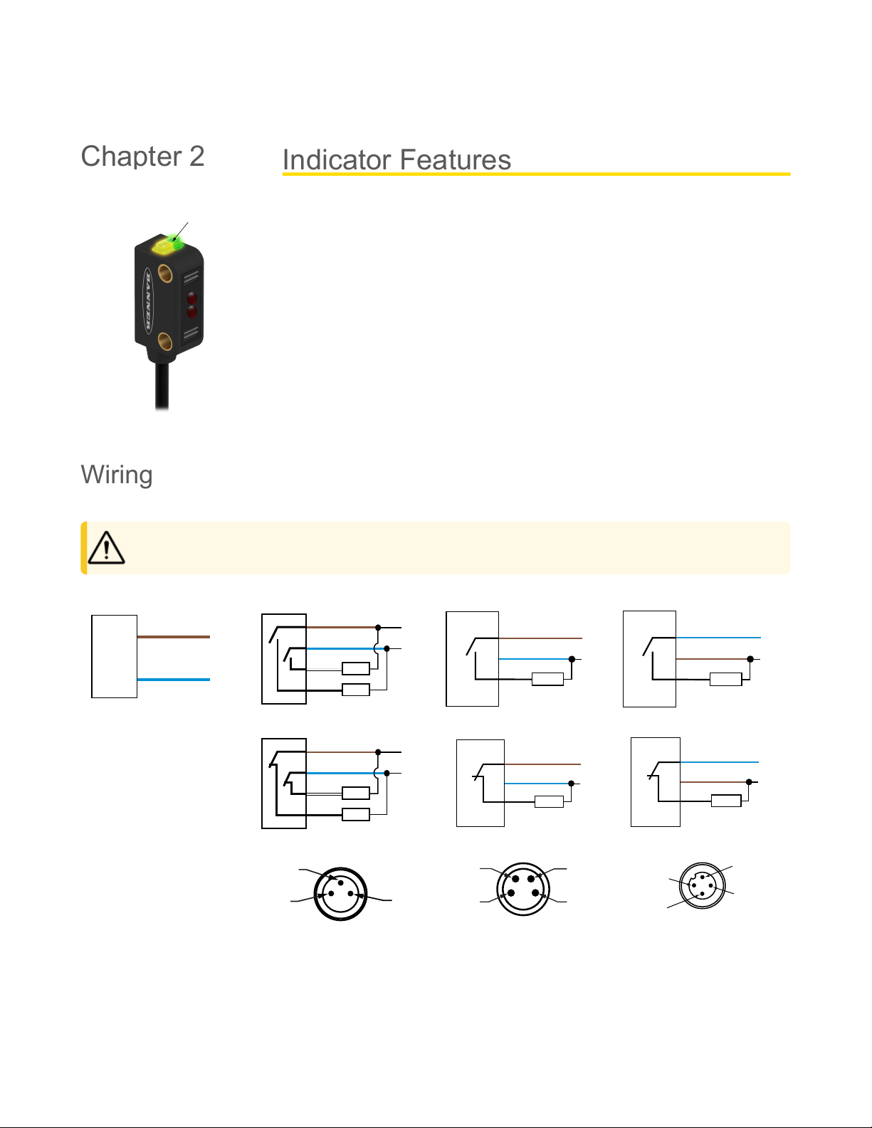
1 - Amber and green LEDs
Green on: power to sensor is on
Amber on: received signal
Amber flashing: marginal signal
Wiring
Emitters have no connection to black and white.
CAUTION: Observe proper ESD precautions (grounding) when connecting QD models.
Emitters
10–30 V DC
–
+
bn (1)
bu (3)
Bipolar Models, Light Operate
10–30VDC
–
+
bn (1)
bu (3)
wh (2)
bk (4)
Load
Load
PNP Models, Light Operate
10–30 V DC
–
+
bu (3)
bn (1)
bk (4)
Load
NPN Models, Light Operate
10–30 V DC
–
+
bu (3)
bn (1)
bk (4)
Load
Bipolar Models, Dark Operate
10–30VDC
–
+
bn (1)
bu (3)
wh (2)
bk (4)
Load
Load
PNP Models, Dark Operate
10–30 V DC
–
+
bu (3)
bn (1)
bk (4)
Load
NPN Models, Dark Operate
10–30 V DC
–
+
bu (3)
bn (1)
bk (4)
Load
Key
1 = Brown
2 = White
3 = Blue
4 = Black
3-pin M8 Male QD
4
1
3
4-pin M8 Male QD
3
2
1
4
4-pin M12 Male QD
1
4
3
2
Indicator Features
Chapter 2
06-May-25 page6of13
DQ12 Series Sensor
© Banner Engineering Corp. All rights reserved.
www.bannerengineering.com
Chapter Contents
FCC Part 15 Class A for Unintentional Radiators................................................................................................................................................. 6
Industry Canada ICES-003(A).............................................................................................................................................................................. 7
Dimensions........................................................................................................................................................................................................... 7
Performance Curves ............................................................................................................................................................................................ 7
Supply Voltage and Current
10 to 30 V DC (10% maximum ripple) at 20 mA maximum
current
Sensing Beam
Visible red, 645 nm
Supply Protection Circuitry
Protected against reverse polarity and transient voltages
Output Configuration
Bipolar (1 NPN and 1 PNP) solid-state output or single output
(PNP or NPN), light operate (LO) or dark operate (DO),
depending on model
Repeatability
125 microseconds
Switching Frequency
Opposed Mode: 385 Hz
LP/LV Mode: 715 Hz
FF Mode: 590 Hz
Output Protection Circuitry
Protected against false pulse on power-up, short-circuit
protected
Output Response Time
Opposed Mode: 1.3 ms ON; 900 µs OFF
LP/LV Mode: 700 µs ON/OFF
FF Mode: 850 µs ON/OFF
120 ms delay on power-up; outputs do not conduct during this
time
Construction
Polarized Retro Models: Polyamide housing with glass lens
All Other Models: Polyamide housing with polycarbonate lens
Output Ratings
OFF-state leakage current:
NPN: 10 µA
PNP: 10 µA
ON-state saturation voltage:
NPN: 2 V at 50 mA
PNP: 2 V at 50 mA
Vibration and Mechanical Shock
Connections
Standard Models: 2 m (6.5 ft) or 9 m (30 ft) attached PVC
cable, or 150 mm (6 in) cable with M8 or M12 threaded
connection, depending on the model ordered
Environmental Rating
Standard Models: IEC IP67
Conditions
Operating Temperature: –20°Cto+55°C(–4°Fto+131°F)
Storage Temperature: –30°Cto+75°C(–22°Fto+167°F)
95% at +50 °C maximum relative humidity (non-condensing)
Certifications
Banner Engineering BV
Park Lane, Culliganlaan 2F bus 3
1831 Diegem, BELGIUM
Turck Banner LTD Blenheim House
Blenheim Court
Wickford, Essex SS11 8YT
GREAT BRITAIN
Required Overcurrent Protection
WARNING: Electrical connections must
be made by qualified personnel in
accordance with local and national
electricalcodesandregulations.
Overcurrent protection is required to be provided by end
productapplicationperthesuppliedtable.
Overcurrent protection may be provided with external fusing
or via Current Limiting, Class 2 Power Supply.
Supply wiring leads < 24 AWG shall not be spliced.
For additional product support, go
towww.bannerengineering.com.
Supply
Wiring
(AWG)
Required Overcurrent
Protection (A)
Supply
Wiring
(AWG)
Required Overcurrent
Protection (A)
20 5.0 26 1.0
22 3.0 28 0.8
24 1.0 30 0.5
FCC Part 15 Class A for Unintentional Radiators
This equipment has been tested and found to comply with the limits for a Class A digital device, pursuant to Part 15 of the FCC Rules. These limits are designed
to provide reasonable protection against harmful interference when the equipment is operated in a commercial environment. This equipment generates, uses,
and can radiate radio frequency energy and, if not installed and used in accordance with the instruction manual, may cause harmful interference to radio
communications. Operation of this equipment in a residential area is likely to cause harmful interference in which case the user will be required to correct the
interference at his own expense.
(Part15.21)Anychangesormodificationsnotexpresslyapprovedbythepartyresponsibleforcompliancecouldvoidtheuser’sauthoritytooperatethis
equipment.
Specifications
Chapter 3
Specifications DQ12 Series Sensor
06-May-25 page7of13© Banner Engineering Corp. All rights reserved.
www.bannerengineering.com
Industry Canada ICES-003(A)
This device complies with CAN ICES-3 (A)/NMB-3(A). Operation is subject to the following two conditions: 1) This device may not cause harmful interference;
and 2) This device must accept any interference received, including interference that may cause undesired operation.
Cet appareil est conforme à la norme NMB-3(A). Le fonctionnement est soumis aux deux conditions suivantes : (1) ce dispositif ne peut pas occasionner
d'interférences, et (2) il doit tolérer toute interférence, y compris celles susceptibles de provoquer un fonctionnement non souhaité du dispositif.
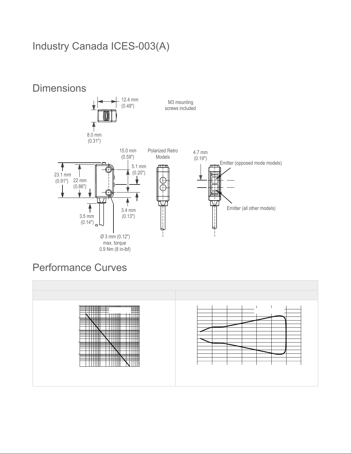
Dimensions
3.5 mm
(0.14")
22 mm
(0.86")
23.1 mm
(0.91")
3.4 mm
(0.13")
5.1 mm
(0.20")
15.0 mm
(0.59")
4.7 mm
(0.19")
Polarized Retro
Models
M3 mounting
screws included
8.0 mm
(0.31")
12.4 mm
(0.49")
Ø 3 mm (0.12")
max. torque
0.9 Nm (8 in-lbf)
Emitter (opposed mode models)
Emitter (all other models)
Performance Curves
Opposed Mode
Excess Gain Beam Pattern
1
10
100
0.1 m
0.33'
0.01 m
0.03'
1 m
3.3'
10 m
33'
1000
10000
100000
DISTANCE
EXCESS GAIN
DQ12 E-R..
2.5 m 3.0 m 3.5 m 2.0 m 1.5 m 1.0 m 0.5 m 0
0
50 mm
100 mm
150 mm
50 mm
100 mm
150 mm
0
2.0"
3.9"
5.9"
2.0"
3.9"
5.9"
DISTANCE
DQ12 E & R..
1.64' 3.28' 4.92' 6.56' 8.20' 9.84' 11.48'
Retroreflective and polarized retroreflective performance is based on the use of a model BRT-60X40C retroreflector.