770715-EM-Eye-ESD-Event-Meter-Guide.pdf - 第3页
TB-91 19 Page 3 of 10 © 2024 DESCO INDUSTRIES INC Employee Owned SCS - 926 JR Industrial Drive, Sanford, NC 27332 East: (919) 718-0000 | West: (909) 627-9634 • Website: StaticControl.com Power Supply and Charger Use only…

TB-9119 Page 2 of 10
© 2024 DESCO INDUSTRIES INC
Employee Owned
SCS - 926 JR Industrial Drive, Sanford, NC 27332
East: (919) 718-0000 | West: (909) 627-9634 • Website: StaticControl.com
The EM Eye Meter and its accessories are available as
the following item numbers:
Item Description
770715 EM Eye - ESD Event Meter
CTC113-6FT Replacement Remote Antenna
CTC115-6FT High Temp Remote Antenna
CTS001 Replacement Local Antenna
770756 Replacement Power Adapter
Packaging
1 EM Eye Meter
1 ESD Event Sensor
1 Local Antenna
1 Remote Antenna with 6' RF Cable
1 microSD Memory Card
1 microSD to USB Type A Adapter
1 Power Adapter, 5VDC, with interchangeable plugs
(North America, UK/Asia, Europe)
1 Carrying Case
Precautions
• Do not drop the meter. This may damage the device
and will void the warranty.
• Do not discharge directly into the antenna metals as
it may damage the input sensors and will void the
warranty.
• Be cautious in the placement of antenna and the
module heads; align the parts while assembling.
• Do not use sharp objects to touch the screen.
• Do not use a wrench or pliers to screw or unscrew
the antenna. Use your bare hands.
• Do not remove the microSD card while the power is
on. Turn off the meter before removing the microSD
card.
• Do not remove the sensor heads while the power
is on. Turn off the meter before removing and
replacing the heads.
Attaching the Sensor Heads
Keep in mind the following when using the modular
sensor heads.
BEFORE CONNECTING TO AN INPUT SOURCE,
TOUCH THE OUTSIDE SURFACE OF THE EM EYE
METER INPUT CONNECTOR. THIS WILL HELP
PREVENT ESD SHOCK TO THE METER.
1. The power must be turned off when changing the
sensor heads.
2. Make sure to gently plug or unplug EM Eye Meter
and the sensor heads.
3. Plug or unplug the sensor heads by firmly gripping
them. Then fit the sensor over the EM Eye unit. Do
not grab the antenna for plugging and unplugging
the sensor heads.
4. If the antenna is separated from the sensor head,
reattach it when the sensor head is securely in
place.
Attaching the Antenna
In order to avoid damaging the EM Eye Meter,
installation and replacement of the antenna must be
done with great care. An excessive amount of force
or improper installation may permanently damage the
meter.
Attach the antenna to the input connector by simply
screwing it in by hand.
DO NOT OVERTIGHTEN THE CONNECTION. Screw
in the antenna firmly but gently. Do not use any tools
other than your hand to attach and detach the antenna.
TB-9119 Page 3 of 10
© 2024 DESCO INDUSTRIES INC
Employee Owned
SCS - 926 JR Industrial Drive, Sanford, NC 27332
East: (919) 718-0000 | West: (909) 627-9634 • Website: StaticControl.com
Power Supply and Charger
Use only the power supply that comes with the EM Eye
Meter. Do not use any other power supply as it may
damage the meter.
Battery Care - Charging for the first time
NOTE: The power switch must be in the ON position
when charging the battery. To improve the battery life
we recommend performing three fully charge-discharge
cycles. For example: fully charge the meter for two
hours or overnight, then use the meter until it is fully
discharged (do not recharge it at half-charge-life).
Repeat this step two times. It would normally take two
hours to fully charge the battery, but since the meter
power is on while charging; it would extend the charge
time to four hours. Succeeding charging would be at any
duration. Use only the supplied charger.
Power On
Use the slide switch at the bottom of the meter to power
the device. If a new sensor was installed, a sequence
of initialization will take place for the first time for
approximately ten seconds. After that, the switch-on
action will take approximately three seconds. The main
display screen appears after the initialization and a
beep will sound. The EM Eye Meter will then perform a
battery check. If the battery is too low to provide reliable
operation, it will not turn on. The screen will go white
momentarily and then the meter will power up. After the
initial power up, the meter will go directly to the main
screen.
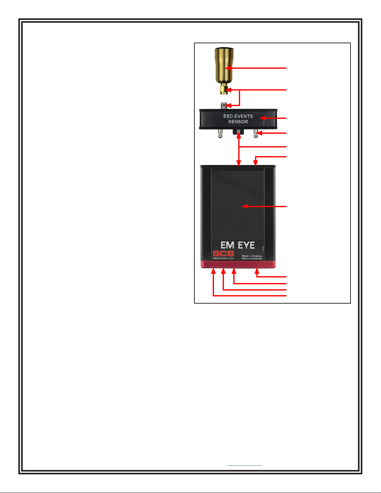
Features and Components
Figure 5. EM Eye features and components
Local directional antenna
Sensor module
SMA connectors
Alignment pin
Communication connectors
Alignment hole
Touchscreen display
microSD memory slot
Headphone jack
Power slide switch
Power jack
TB-9119 Page 4 of 10
© 2024 DESCO INDUSTRIES INC
Employee Owned
SCS - 926 JR Industrial Drive, Sanford, NC 27332
East: (919) 718-0000 | West: (909) 627-9634 • Website: StaticControl.com
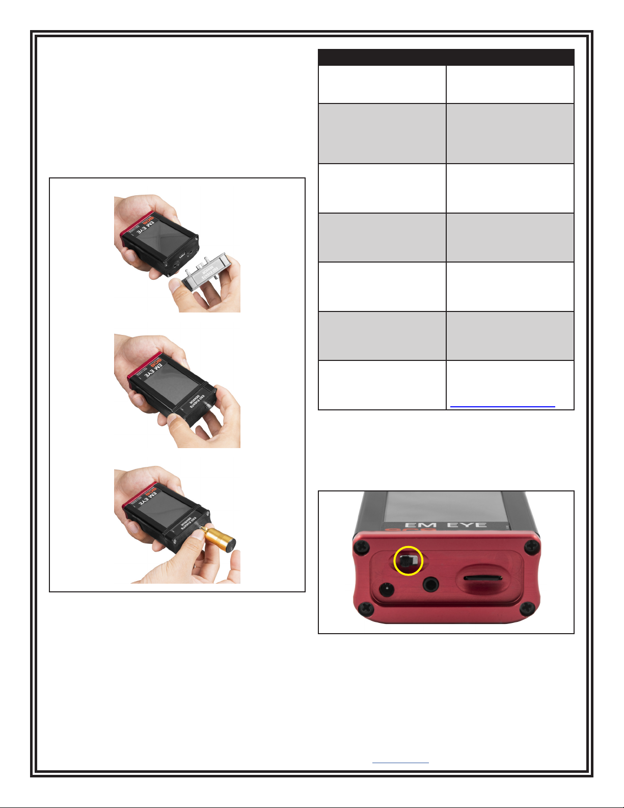
Modular Assembly and Disassembly
1. Position the sensor head so that the dowel pins
align with the holes.
2. With the initial head midway through, reposition it so
that it is parallel to the body. Press the sensor head
firmly against the body until both surfaces are flat
with each other.
3. Insert and screw in the antenna making sure that it
is not too tight or too loose. Do not use any tools.
Error Message Reason for Error
ERROR: Sensor is
disconnected. Click here
to turn device o.
The meter is turned
on without the sensor
module.
ERROR: Card was
removed. Data may be
lost and card could be
damaged. Click here to
close the window.
The storage card
(microSD) is removed
while the meter is
powered on.
WARNING: No memory
card. You can add it at
any time. Click here to
close the window.
The meter is turned on
with no storage card in
place.
PREPARING CARD FOR
RECORDING!!! DO NOT
REMOVE!!! PLEASE
WAIT.
A new card is inserted or
when a card is empty.
WARNING: This card
contains the data.
Remove the card or click
here to erase the data.
Inserting a card that has
contents other than the
EM Eye Meter les.
ERROR: Invalid memory
card. Format or replace
it. Click here to close the
window.
The card is not formatted
to FAT32. Formatting is
done using the PC.
ERROR!!! STACK
OVERFLOWED. Click
here to turn device o.
This is a fatal error. If
it appears even after
resetting, please contact
SCS Customer Service.
Power Reset
If the EM Eye Meter locks up or the display freezes,
cycle the power to the meter by sliding its power switch
to the OFF position and back to the ON position.
If the assembly is not done correctly, one of the
following error and warning messages may appear. To
correct, follow the instructions as indicated within the
message.
Figure 7. Location of the power switch at the bottom of
the EM Eye Meter
Figure 6. Attaching the sensor module to the EM Eye
Meter