00194598-01.pdf - 第49页
Ceramic substrate centering SIPLACE S- 27 HM 2 Retrofit instructions: ceramic substrate centering for SIPLACE S-27 HM 12/2004 Edition 49 : Connect the co mpress ed air hos e to the cer amic sub strate ce ntering an d con…
2 Retrofit instructions: ceramic substrate centering for SIPLACE S-27 HM Ceramic substrate centering SIPLACE S-27 HM
12/2004 Edition
48
: Please check the plug configuration before plugging in.
2
: Fit the cover to the cable duct and to the conversion board.
2
If the lifting table bed that you removed already has the holes for the ceramic substrate centering,
it may be refitted. If there are no holes, then the new lifting table bed with the holes must be fitted.2
: Install the appropriate lifting table bed.
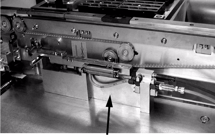
: Fix the ceramic substrate centering to the lifting table bed using the pins (photograph below).
: Screw it firmly to the lifting table bed using two screws.
2
2
2
2
Coding 1 2
Jumper brown 3 4 brown Jumper
Sensor brown 5 6
Sensor black 7 8
910
11 12
Sensor blue 13 14 black Solenoid valve
Solenoid valve black/red 15 16
Coding 17 18
Ceramic substrate centering
Ceramic substrate centering SIPLACE S-27 HM 2 Retrofit instructions: ceramic substrate centering for SIPLACE S-27 HM
12/2004 Edition
49
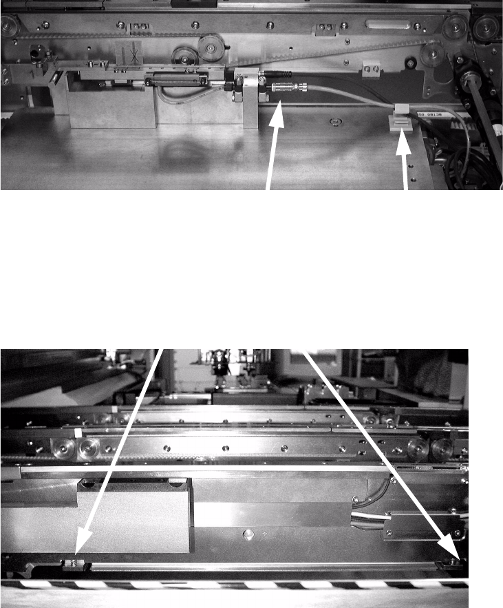
: Connect the compressed air hose to the ceramic substrate centering and connect electrically.
2
2.5.1 Installing the lifting table travel limiter
2
2
2
2
2
2
2
2
Connections
Cable clamp
PCB clamp
2 Retrofit instructions: ceramic substrate centering for SIPLACE S-27 HM Ceramic substrate centering SIPLACE S-27 HM
12/2004 Edition
50
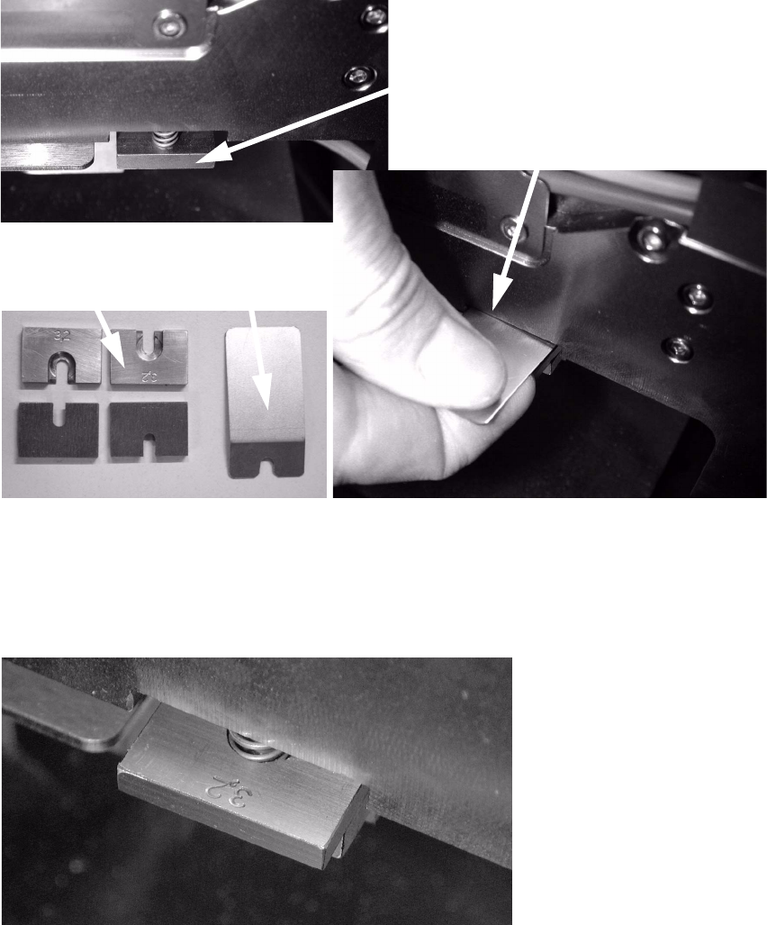
: Use the tool to lift the compression spring on the PCB clamp as far as the stop.
2
2
: Insert the travel limiter. You must feel the compression spring snap into place.
2
: Remove the tool.
: Insert two travel limiters per conveyor side wall and placement area.
2
PCB clamp
Lift the compression spring
Travel limiter
Tools
00366960-02-xx Travel limiter 2.5 mm for SIPLACE HS-60/S-27 HM