manual-rhs-rework-hand-support-0028766_ID-221999.pdf - 第3页
R R R R L L R R L L R R L L L L R R L L JT T JT T JT T JT T JT T R R R R L L R R L L R R L L L L R R L L JT T JT T JT T JT T JT T Ar ticulat ed Hand Res t Ar m Height Adj ustment Flange Shaf t Base Hand Rest Features Hea…
Articulated
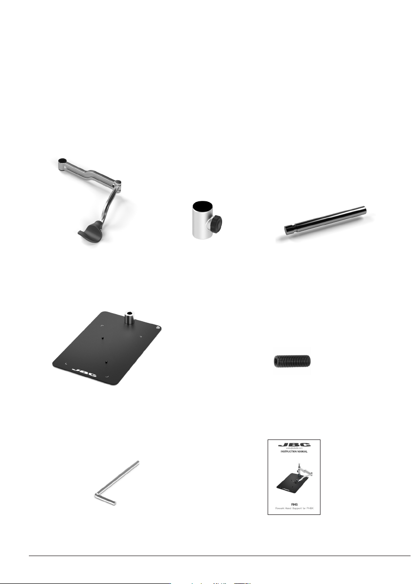
Hand Rest Arm ................ 1 unit
Height Adj. Flange ......w. 1
unit
Ref. 0023991
Shaft .............................. 1 unit
Ref. 0024007
Base PHSE compatible ......................... 1 unit Headless Screw ....................................... 1 unit
Ref. 0 017057
Allen key ..................................................... 1 unit
Ref. 0013609
Manual ......................................................... 1 unit
Ref. 0028766
Packing List
The following items are included:
This manual corresponds to the following reference:
RHS-A
2
R
R
R
R
L
L
R
R
L
L
R
R
L
L
L
L
R
R
L
L
JTT
JTT
JTT
JTT
JTT
R
R
R
R
L
L
R
R
L
L
R
R
L
L
L
L
R
R
L
L
JTT
JTT
JTT
JTT
JTT
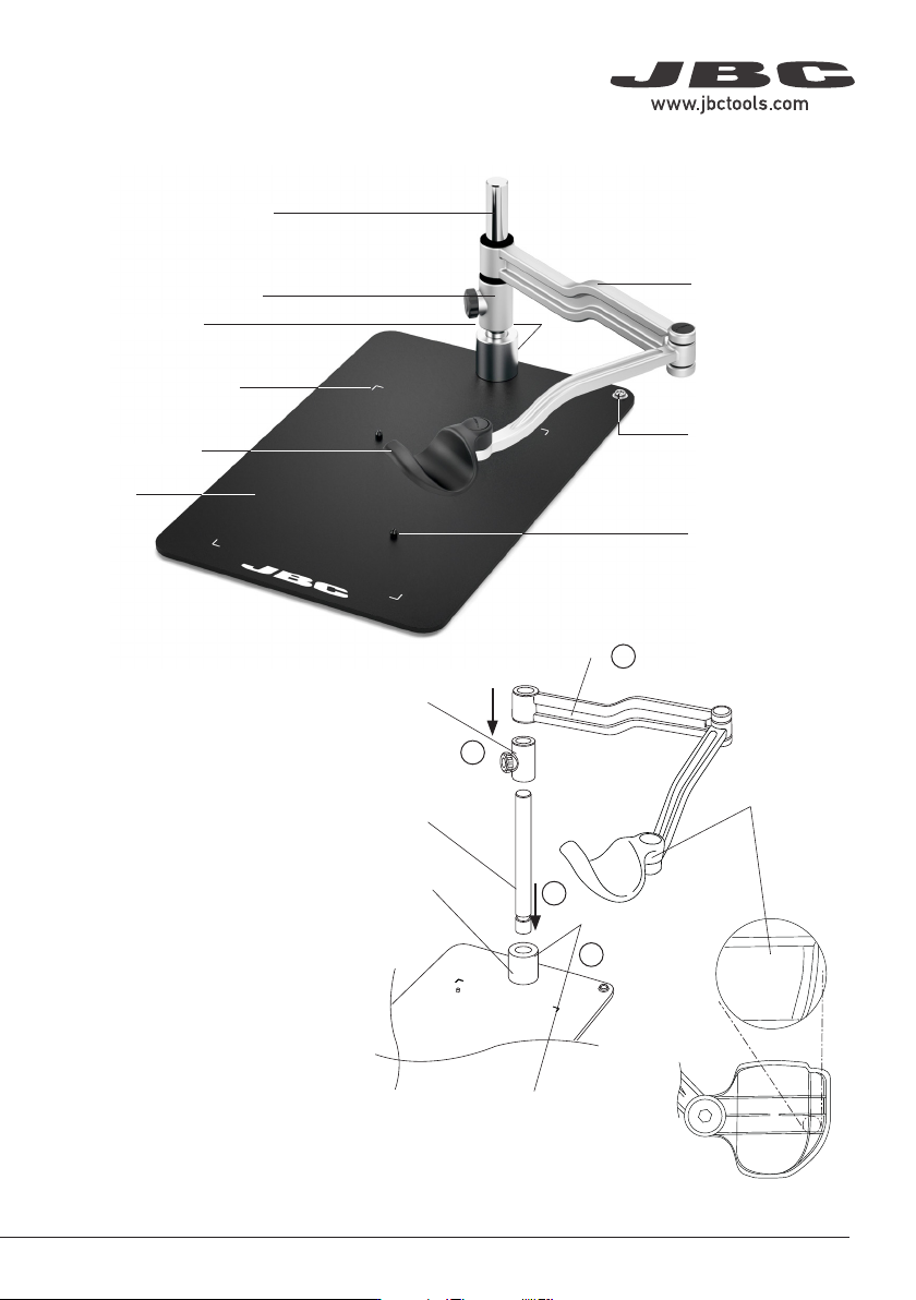
Articulated Hand
Rest Arm
Height Adjustment Flange
Shaft
Base
Hand Rest
Features
Headless Screw
Positioning Bolds
Printed Corner Guides
Assembly
ESD Connector
(connect to ESD
Common Grounding
Point)
Setting up the Articulated
Hand Rest
Fit the shaft into the base bushing
(1) and tighten the headless screw
(2). Then assemble first the height
adjustment flange (3) and finally the
hand rest arm (4) onto the shaft.
The hand rest arm position should
be as shown in the image. The right
hand rest is marked at its bottom
side with the letter “R”.
Headless Screw
(at the back)
Shaft
Base
Bushing
Height
Adjustment
Flange
Hand Rest
Arm
Bottom View
Right Hand
Rest
1
2
3
4
3
40 mm
50 mm
60 mm
80 mm
100 mm
130 mm
130 mm
para manuales - color gris
200 mm
300 mm
R
R
R
R
L
L
R
R
L
L
R
R
L
L
L
L
R
R
L
L
JTT
JTT
JTT
JTT
JTT
R
R
R
R
L
L
R
R
L
L
R
R
L
L
L
L
R
R
L
L
JTT
JTT
JTT
JTT
JTT
R
R
R
R
L
L
R
R
L
L
R
R
L
L
L
L
R
R
L
L
JTT
JTT
JTT
JTT
JTT
R
R
R
R
L
L
R
R
L
L
R
R
L
L
L
L
R
R
L
L
JTT
JTT
JTT
JTT
JTT
R
R
R
R
L
L
R
R
L
L
R
R
L
L
L
L
R
R
L
L
JTT
JTT
JTT
JTT
JTT
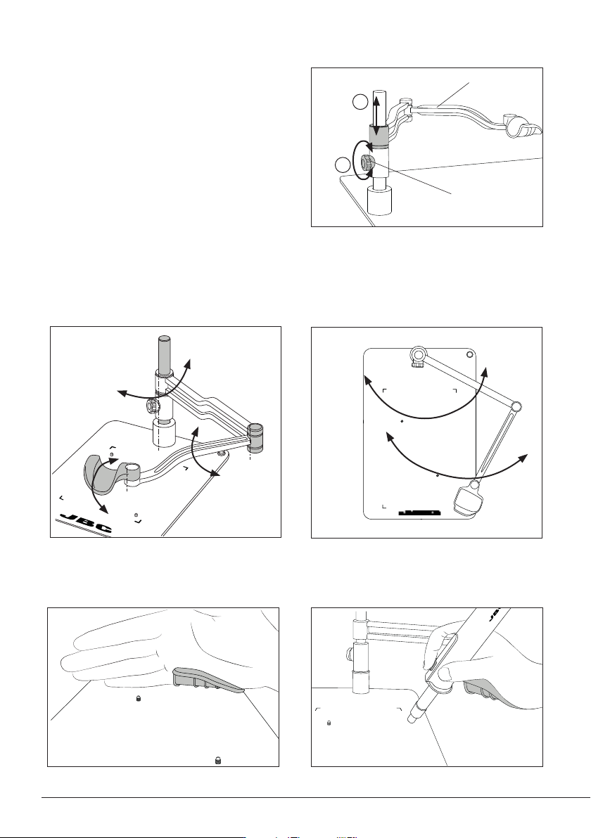
Work Position Adjustment
Position the arm and tighten the knobs.
The correct hand work position is shown in the following images:
Knob
Height Adjustment
According to your work needs the articulated
hand rest allows adjustment for different
heights through the vertical axis.
Slide the arm to the appropriate height (1) and
secure it by tightening the knob (2) to guarantee
stability.
Arm
1
2
RHN arm allows adjustment for different positions according to your work needs. The articulated arm
covers all work areas.
4