manual-rhs-rework-hand-support-0028766_ID-221999.pdf - 第4页
R R R R L L R R L L R R L L L L R R L L JT T JT T JT T JT T JT T R R R R L L R R L L R R L L L L R R L L JT T JT T JT T JT T JT T R R R R L L R R L L R R L L L L R R L L JT T JT T JT T JT T JT T R R R R L L R R L L R R L…
R
R
R
R
L
L
R
R
L
L
R
R
L
L
L
L
R
R
L
L
JTT
JTT
JTT
JTT
JTT
R
R
R
R
L
L
R
R
L
L
R
R
L
L
L
L
R
R
L
L
JTT
JTT
JTT
JTT
JTT
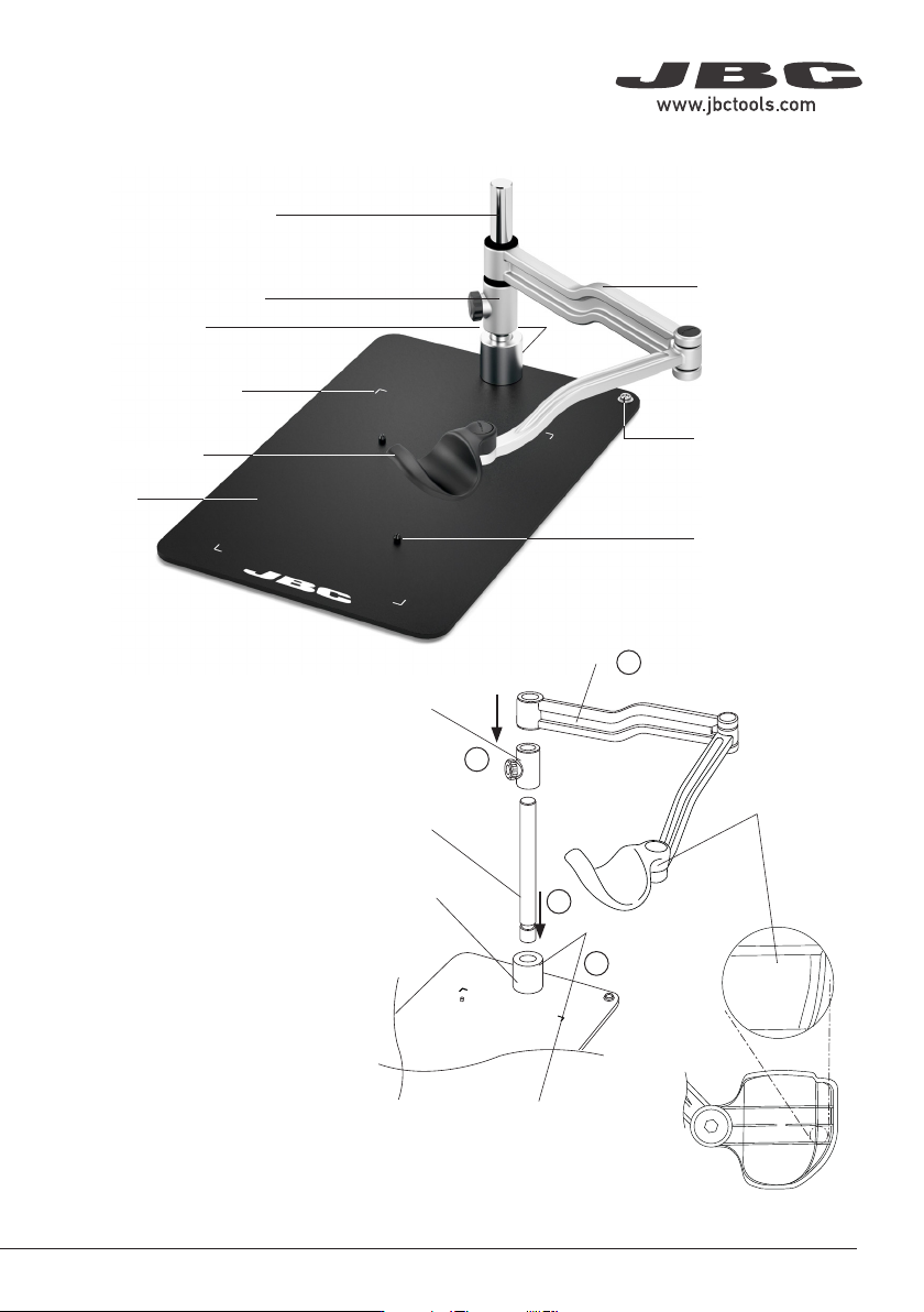
Articulated Hand
Rest Arm
Height Adjustment Flange
Shaft
Base
Hand Rest
Features
Headless Screw
Positioning Bolds
Printed Corner Guides
Assembly
ESD Connector
(connect to ESD
Common Grounding
Point)
Setting up the Articulated
Hand Rest
Fit the shaft into the base bushing
(1) and tighten the headless screw
(2). Then assemble first the height
adjustment flange (3) and finally the
hand rest arm (4) onto the shaft.
The hand rest arm position should
be as shown in the image. The right
hand rest is marked at its bottom
side with the letter “R”.
Headless Screw
(at the back)
Shaft
Base
Bushing
Height
Adjustment
Flange
Hand Rest
Arm
Bottom View
Right Hand
Rest
1
2
3
4
3
40 mm
50 mm
60 mm
80 mm
100 mm
130 mm
130 mm
para manuales - color gris
200 mm
300 mm
R
R
R
R
L
L
R
R
L
L
R
R
L
L
L
L
R
R
L
L
JTT
JTT
JTT
JTT
JTT
R
R
R
R
L
L
R
R
L
L
R
R
L
L
L
L
R
R
L
L
JTT
JTT
JTT
JTT
JTT
R
R
R
R
L
L
R
R
L
L
R
R
L
L
L
L
R
R
L
L
JTT
JTT
JTT
JTT
JTT
R
R
R
R
L
L
R
R
L
L
R
R
L
L
L
L
R
R
L
L
JTT
JTT
JTT
JTT
JTT
R
R
R
R
L
L
R
R
L
L
R
R
L
L
L
L
R
R
L
L
JTT
JTT
JTT
JTT
JTT
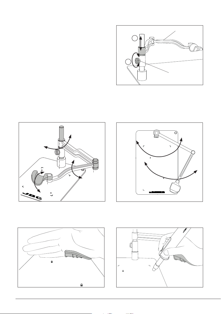
Work Position Adjustment
Position the arm and tighten the knobs.
The correct hand work position is shown in the following images:
Knob
Height Adjustment
According to your work needs the articulated
hand rest allows adjustment for different
heights through the vertical axis.
Slide the arm to the appropriate height (1) and
secure it by tightening the knob (2) to guarantee
stability.
Arm
1
2
RHN arm allows adjustment for different positions according to your work needs. The articulated arm
covers all work areas.
4
R
R
R
R
L
L
R
R
L
L
R
R
L
L
L
L
R
R
L
L
JTT
JTT
JTT
JTT
JTT
R
R
R
R
L
L
R
R
L
L
R
R
L
L
L
L
R
R
L
L
JTT
JTT
JTT
JTT
JTT
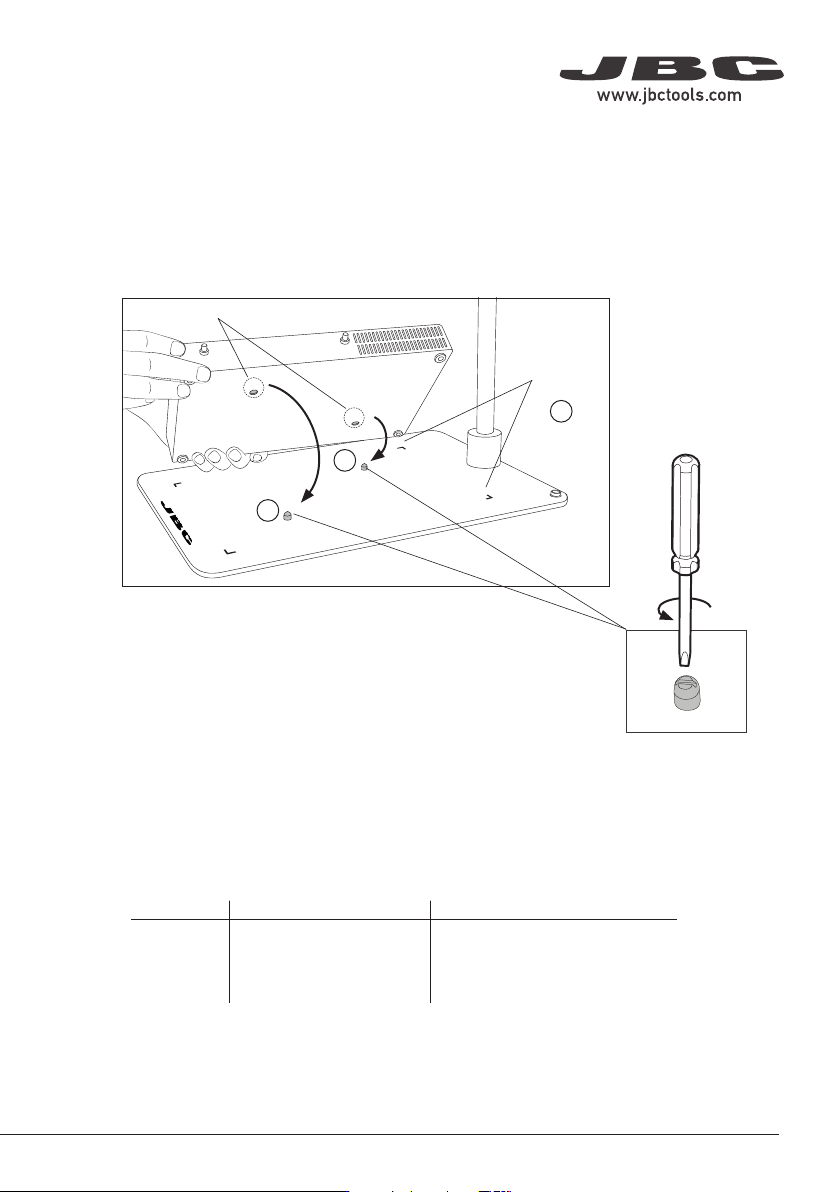
Preheater Positioning
Positioning Caps
If a fixed preheater position
is not wanted the positioning
bolts can be removed
with a screwdriver.
Corner
Guides
1
2
1
Positioning Bolds
Note: for each preheater size, there are different articulated hand rests with different base dimensions
available.
Preheater Articulated Hand Rest Base Dimension
PHNE RHN 310 x 239 mm / 12.20 x 9.41 in
PHSE RHS 410 x 270 mm / 16.14 x 10.63 in
PHBE RHB 550 x 480 mm / 21.65 x 18.90 in
RHS has been designed to work together with PHS
Fit PHSE onto the positioning bolts (1) for proper alignment. The four corner guides (2) help to place
the heater unit in its position.
5
40 mm
50 mm
60 mm
80 mm
100 mm
130 mm
130 mm
para manuales - color gris
200 mm
300 mm