00193431-03.pdf - 第29页
HS-50 Modification Long Board Option 2 Assembly instructions Long Board Option SIPLACE HS-50 03/2007 Edition 29 : Pull out the BERO until the LED on the BERO goes out. 2 Fig. 2.10 - 1 New stopper unit : Disconnect t he a…
2 Assembly instructions Long Board Option SIPLACE HS-50 HS-50 Modification Long Board Option
03/2007 Edition
28
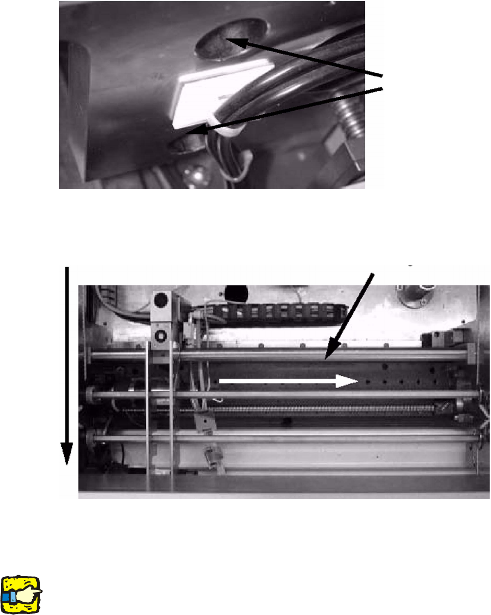
: Remove the two screws on the guide pillars.
2
: Push the guide pillars to the right (viewed in the transport direction).
2
2
: Remove the old stopper. This is no longer required.
: Push the new stopper unit for long PCBs onto the pillars, and fix the pillars in place once more.
2
The stopper BERO must not be activated when the stopper is retracted. 2
2
Screws on the
guide pillars
Transport direction
Guide pillars
HS-50 Modification Long Board Option 2 Assembly instructions Long Board Option SIPLACE HS-50
03/2007 Edition
29
: Pull out the BERO until the LED on the BERO goes out.
2
Fig. 2.10 - 1 New stopper unit
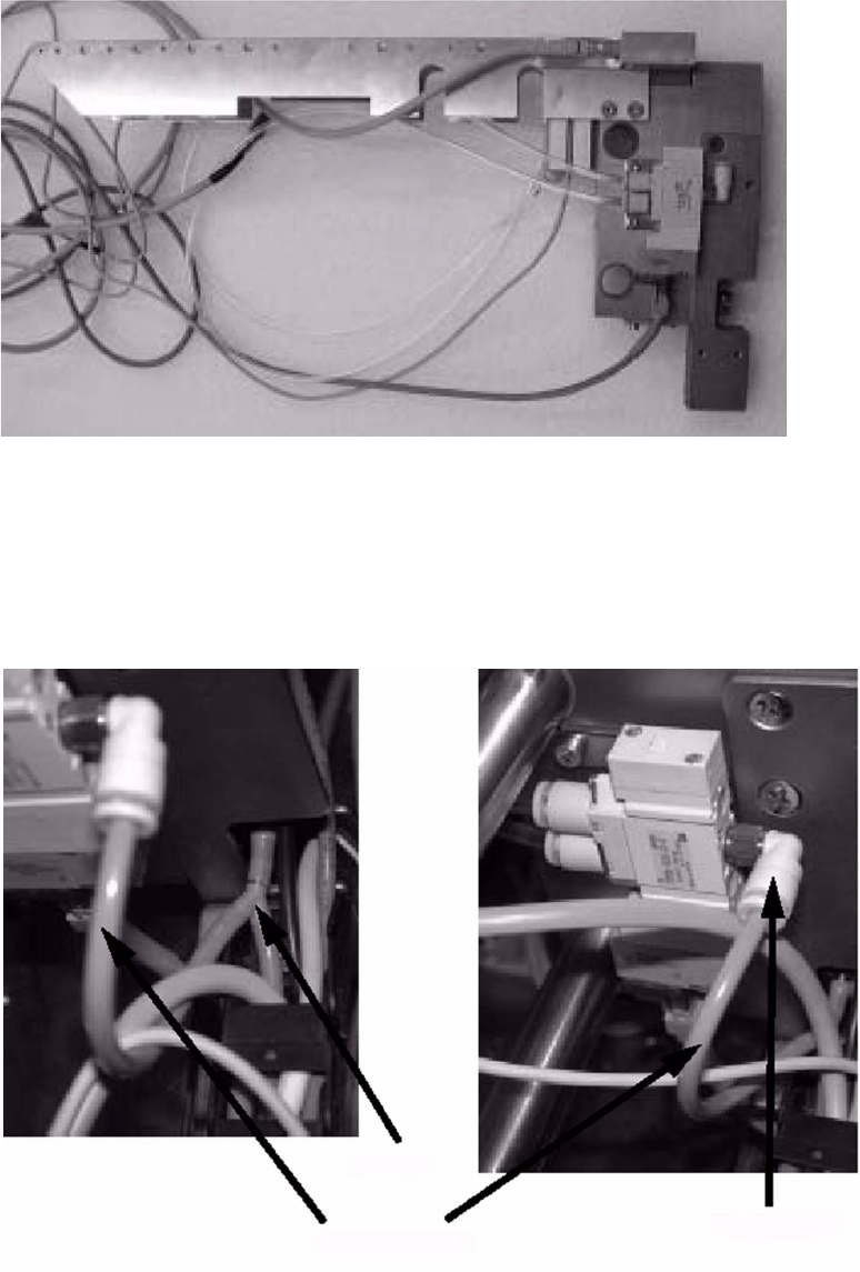
: Disconnect the air hose.
: Fit the Y adapter with the additional hose, and connect the additional hose to the new valve.
2
2
Y adapter
Additional hose
New valve
2 Assembly instructions Long Board Option SIPLACE HS-50 HS-50 Modification Long Board Option
03/2007 Edition
30
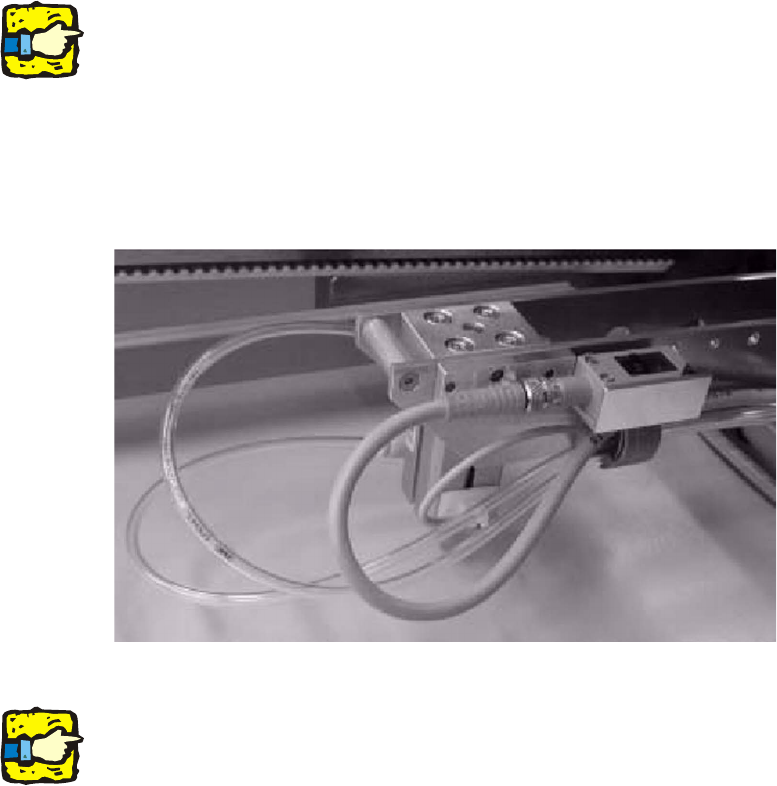
: Thread the connecting cable and compressed air hose through the power chain.
2
Do not attach the plugs to the connecting cables until they have been laid, otherwise they will not
fit through the power chain. 2
The BERO can be fitted in different positions, so it is sensible to use the foremost position in the
transport direction (with the longest cables) when laying the cables. 2
2
: Fit the BERO in the foremost position.
2
2
2
Run the cables and lines in a gentle arc to prevent kinks. 2
2
2
2
2
2
2
2
2
2
2
2
2