00193431-03.pdf - 第33页
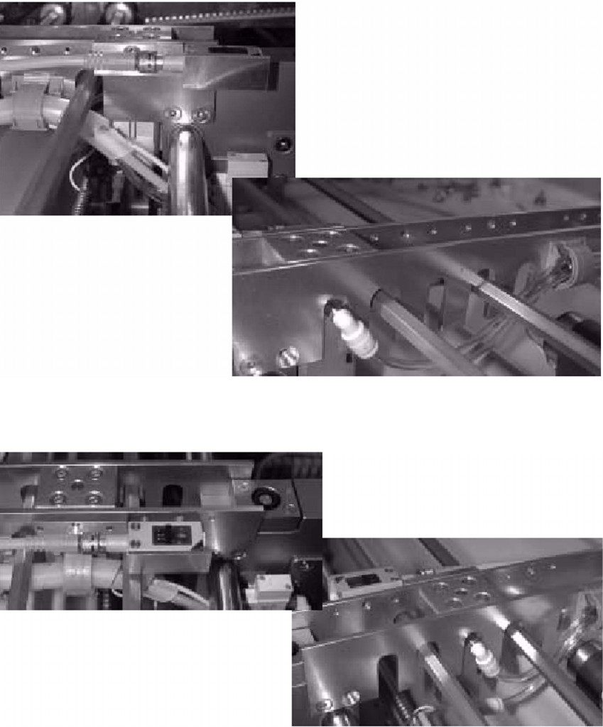
HS-50 Modification Long Board Option 2 Assembly instructions Long Board Option SIPLACE HS-50 03/2007 Edition 33 Item 3: 2 2 2 Item 4: 2 2 2 2 Restriction at position 3: Minimum PCB wid th set to 140 mm
2 Assembly instructions Long Board Option SIPLACE HS-50 HS-50 Modification Long Board Option
03/2007 Edition
32
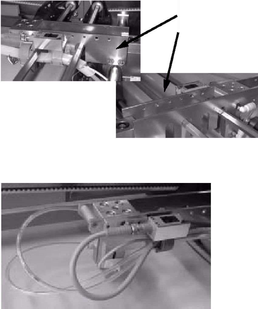
: Test all the possible positions for the BERO. Make sure that the cables and lines do not hang
loose in any of the positions.
In position 1, the left-hand plate for positioning the scanning unit must be released.
2
Item 1: 2
2
Item 2: 2
2
HS-50 Modification Long Board Option 2 Assembly instructions Long Board Option SIPLACE HS-50
03/2007 Edition
33
Item 3: 2
2
2
Item 4: 2
2
2
2
Restriction at
position 3:
Minimum PCB width
set to 140 mm
2 Assembly instructions Long Board Option SIPLACE HS-50 HS-50 Modification Long Board Option
03/2007 Edition
34
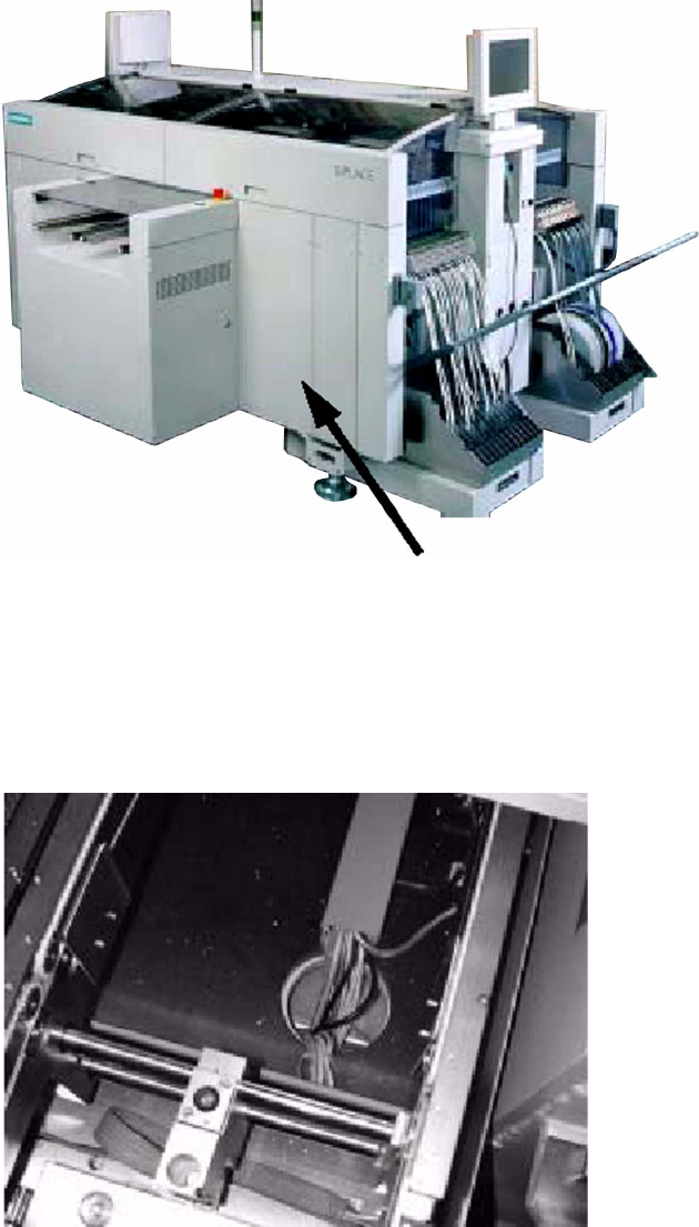
2.1.1 Wiring for a machine with HS-50 transport controller conversion board sec-
tor 1, viewed in the transport direction.
2
2
: Run the cables through the power chain and cable duct, and through the opening in the ma-
chine frame to the transport controller conversion board.
2
Transport controller conversion board