Infinity EX Printhead Lift.pdf - 第3页
INFINITY EX PRINTHEAD LIFT MOD ULE MECHANICAL DETAIL Chapter Issue 2 J an 04 Technical Reference Manual 8.3 MECHANICAL DET AIL Head Latches The head latches are electr omagnets fit ted to the printhead down stops. The pu…
INFINITY
EX
PRINTHEAD LIFT MODULE
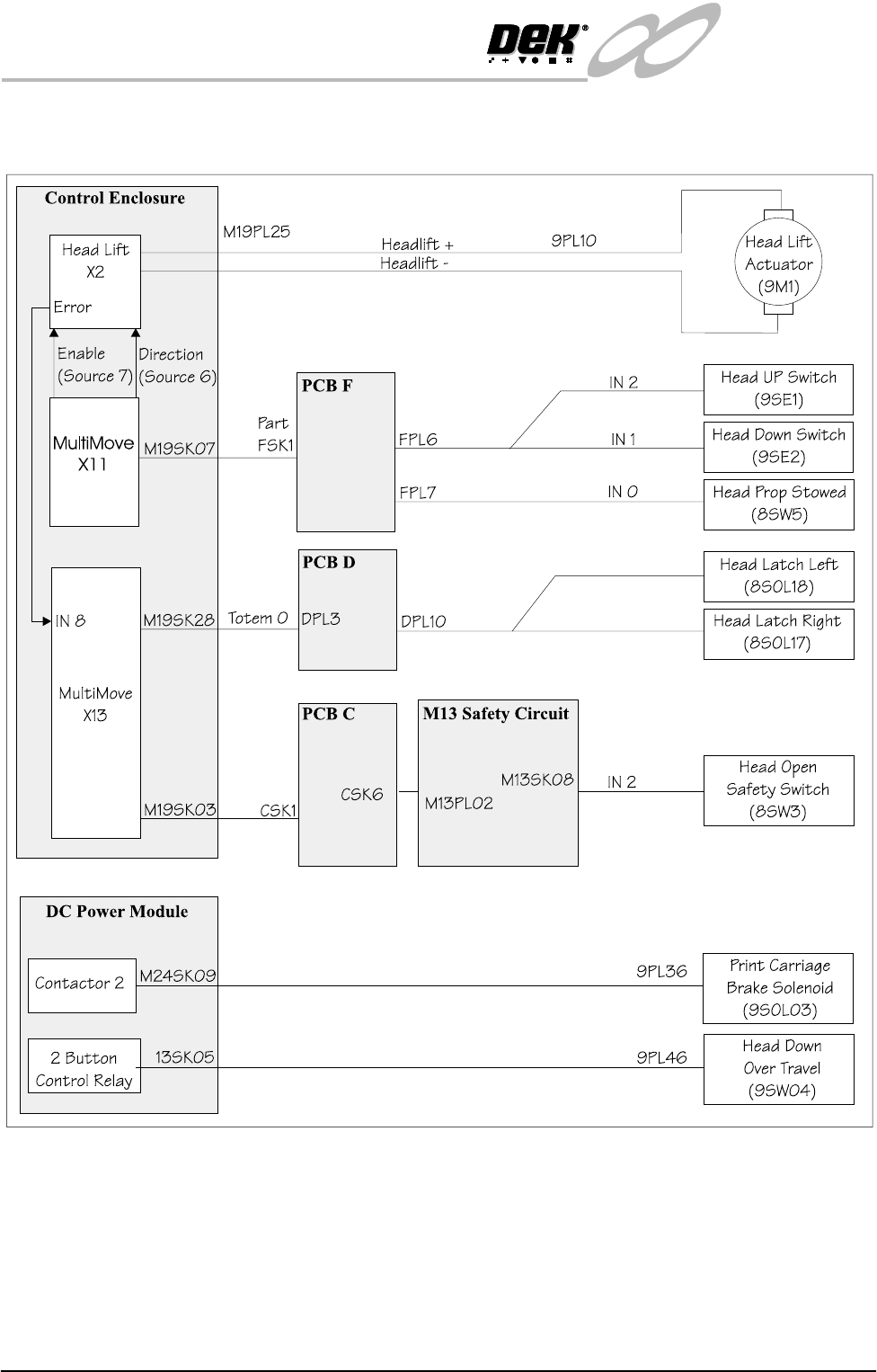
PRINTHEAD SCHEMATIC
8.2 Technical Reference Manual Chapter Issue 2 Jan 04
PRINTHEAD SCHEMATIC
INFINITY
EX
PRINTHEAD LIFT MODULE
MECHANICAL DETAIL
Chapter Issue 2 Jan 04 Technical Reference Manual 8.3
MECHANICAL DETAIL
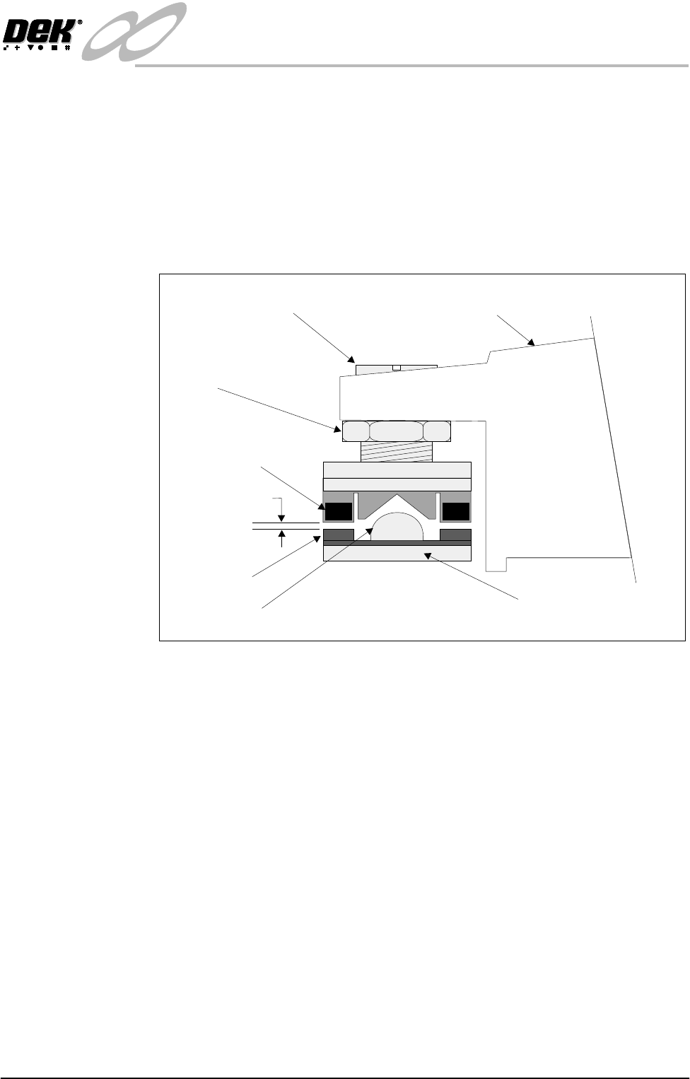
Head Latches The head latches are electromagnets fitted to the printhead down stops. The
purpose of the head latches is to maintain stability of the machine by keeping
the two main castings locked together at the front.
The head down position and therefore the printhead/table level is set by the
spigot around which the magnet is fixed. To ensure that the magnet does not
interfere with the level, a gap of 0.05mm to 0.3mm is set between magnet and
plate with the head down and latches turned off.
Figure 8-1 Printhead Left Hand Latch
Printhead Casting
Printhead Level Adjustment
Locknut
Locating Spigot
Aluminium Base Plate
Electro Magnet
0.05mm - 0.3mm
Sprung Latch
INFINITY
EX
PRINTHEAD LIFT MODULE
ELECTRICAL DETAIL
8.4 Technical Reference Manual Chapter Issue 2 Jan 04
ELECTRICAL DETAIL
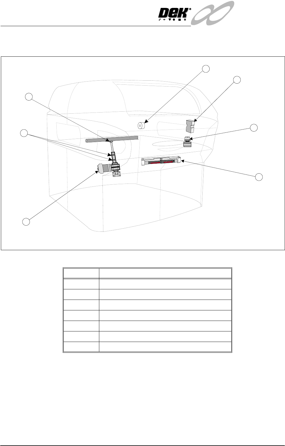
Figure 8-2 Headlift Electrical Component Location
F
R
O
N
T
F
R
O
N
T
F
R
O
N
T
2
1
3
4
5
7
6
Number Description
1 Print Carriage Brake Solenoid
2 Head Up Safety Switch
3 Head Latch - Right (LH opposite [not shown])
4 Head Prop Stowed Sensor (Solid State Microswitch)
5 Head Lift Actuator
6 Head Up and Head Down Switches
7 Head Down Over Travel Switch