Infinity EX Printhead Lift.pdf - 第5页
INFINITY EX PRINTHEAD LIFT MOD ULE ELECTRIC AL DETAIL Chapter Issue 2 J an 04 Technical Reference Manual 8.5 Head Down Over tra v el Switch If the head is lo wered and the printhead down reed swi tch is not seen by the c…
INFINITY
EX
PRINTHEAD LIFT MODULE
ELECTRICAL DETAIL
8.4 Technical Reference Manual Chapter Issue 2 Jan 04
ELECTRICAL DETAIL
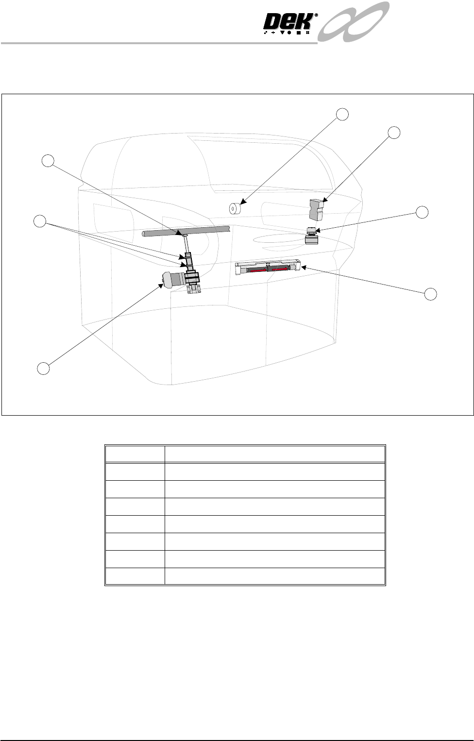
Figure 8-2 Headlift Electrical Component Location
F
R
O
N
T
F
R
O
N
T
F
R
O
N
T
2
1
3
4
5
7
6
Number Description
1 Print Carriage Brake Solenoid
2 Head Up Safety Switch
3 Head Latch - Right (LH opposite [not shown])
4 Head Prop Stowed Sensor (Solid State Microswitch)
5 Head Lift Actuator
6 Head Up and Head Down Switches
7 Head Down Over Travel Switch
INFINITY
EX
PRINTHEAD LIFT MODULE
ELECTRICAL DETAIL
Chapter Issue 2 Jan 04 Technical Reference Manual 8.5
Head Down
Overtravel Switch
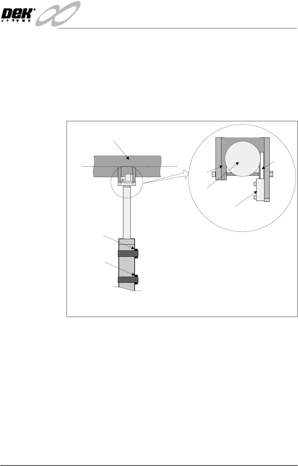
If the head is lowered and the printhead down reed switch is not seen by the
controller, the actuator continues to drive the head down. This action could
result in some machine damage as the actuator plunger would continue to drive
up into the head lift bar. To prevent this the motor output is switched off by the
head down over travel switch. This switch is wired in series with the supply to
the two handed control relay and when activated immediately cuts power to the
motor.
The head down over travel switch also prevents the head lift motor from driving
down should the head become jammed whilst moving.
Figure 8-3 Head Down Overtravel Switch
Printhead Up
Reed Switch
Printhead Down
Reed Switch
Head Lift Bar
Part View on Printhead Actuator
(Viewed from rear of machine)
View on Switch and Clevis
(Plan View)
Clamp
Clevis
Switch
Switch
Tab
INFINITY
EX
PRINTHEAD LIFT MODULE
ELECTRICAL DETAIL
8.6 Technical Reference Manual Chapter Issue 2 Jan 04
Head Prop Stowed
Sensor
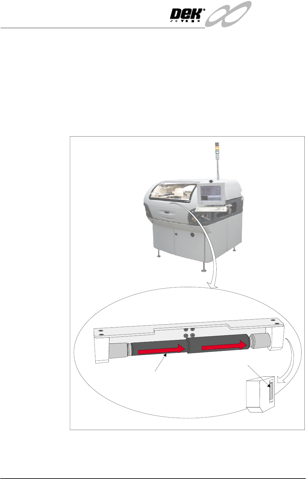
The head prop stowed sensor switch is fitted to prevent inadvertant lowering of
the printhead whilst the head prop is fitted.
If an attempt to lower the printhead is made without the head prop fitted in the
stowage position, the jog buttons are disabled and the warning window ‘Haz-
ardous Operation - The head is about to be lowered. Remove the head prop
and confirm that everyone is standing clear’ remains displayed.
The sensor is of the solid state micro switch type. An internal magnetic source
is moved by an external push button, the resultant magnetic flux is detected and
the output is switched by anopen collector transistor. The switch does not have
the inherent problems of a conventional metal contact arrangement.
Figure 8-4 Head Prop Stowage
Head Prop stowed inside printhead cover
Viewed on Front of Machine
Head Prop
Head Prop Stowed Sensor
RH Support Block
F
R
O
N
T
F
R
O
N
T
F
R
O
N
T