Infinity EX Printhead Lift.pdf - 第6页
INFINITY EX PRINTHEA D LIFT MODU LE ELECTRICA L DETAIL 8.6 Technical Reference Manu al Chapter Issu e 2 Jan 04 Head Pr op Stowed Senso r The head prop stowed sensor switch is f itted to prev ent inadv ertant lo wering of…
INFINITY
EX
PRINTHEAD LIFT MODULE
ELECTRICAL DETAIL
Chapter Issue 2 Jan 04 Technical Reference Manual 8.5
Head Down
Overtravel Switch
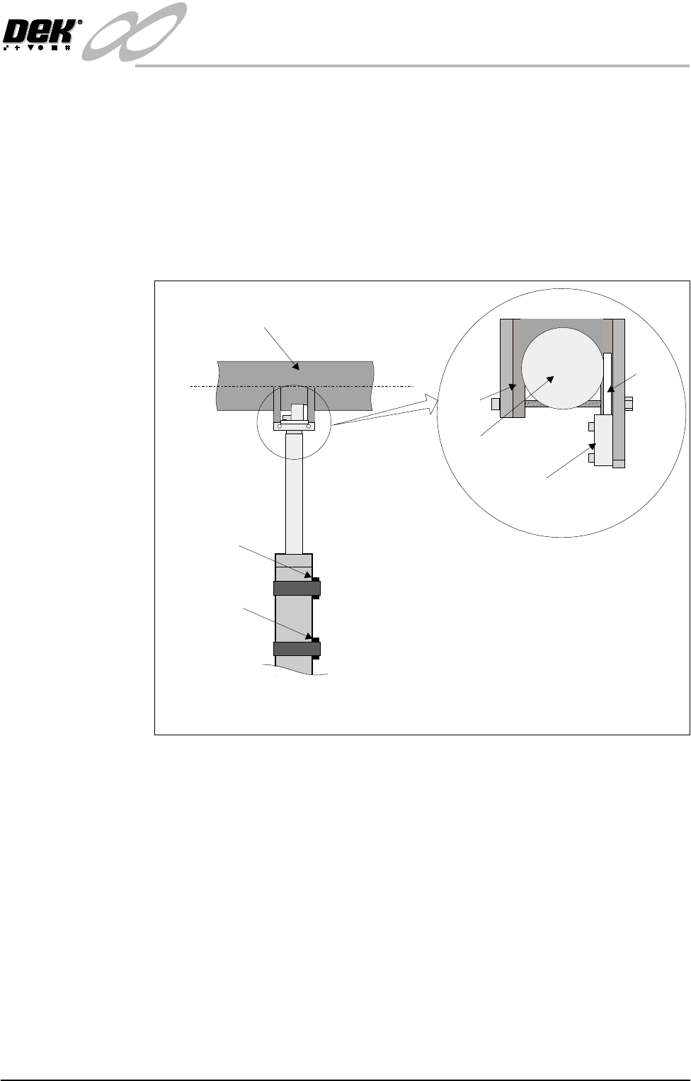
If the head is lowered and the printhead down reed switch is not seen by the
controller, the actuator continues to drive the head down. This action could
result in some machine damage as the actuator plunger would continue to drive
up into the head lift bar. To prevent this the motor output is switched off by the
head down over travel switch. This switch is wired in series with the supply to
the two handed control relay and when activated immediately cuts power to the
motor.
The head down over travel switch also prevents the head lift motor from driving
down should the head become jammed whilst moving.
Figure 8-3 Head Down Overtravel Switch
Printhead Up
Reed Switch
Printhead Down
Reed Switch
Head Lift Bar
Part View on Printhead Actuator
(Viewed from rear of machine)
View on Switch and Clevis
(Plan View)
Clamp
Clevis
Switch
Switch
Tab
INFINITY
EX
PRINTHEAD LIFT MODULE
ELECTRICAL DETAIL
8.6 Technical Reference Manual Chapter Issue 2 Jan 04
Head Prop Stowed
Sensor
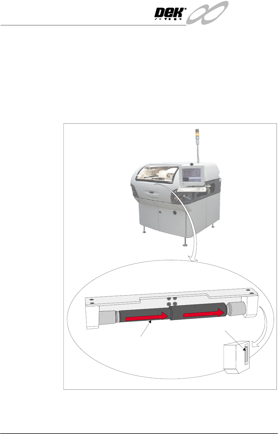
The head prop stowed sensor switch is fitted to prevent inadvertant lowering of
the printhead whilst the head prop is fitted.
If an attempt to lower the printhead is made without the head prop fitted in the
stowage position, the jog buttons are disabled and the warning window ‘Haz-
ardous Operation - The head is about to be lowered. Remove the head prop
and confirm that everyone is standing clear’ remains displayed.
The sensor is of the solid state micro switch type. An internal magnetic source
is moved by an external push button, the resultant magnetic flux is detected and
the output is switched by anopen collector transistor. The switch does not have
the inherent problems of a conventional metal contact arrangement.
Figure 8-4 Head Prop Stowage
Head Prop stowed inside printhead cover
Viewed on Front of Machine
Head Prop
Head Prop Stowed Sensor
RH Support Block
F
R
O
N
T
F
R
O
N
T
F
R
O
N
T
INFINITY
EX
PRINTHEAD LIFT MODULE
ELECTRICAL DETAIL
Chapter Issue 2 Jan 04 Technical Reference Manual 8.7
Head Lift Circuit
Operation
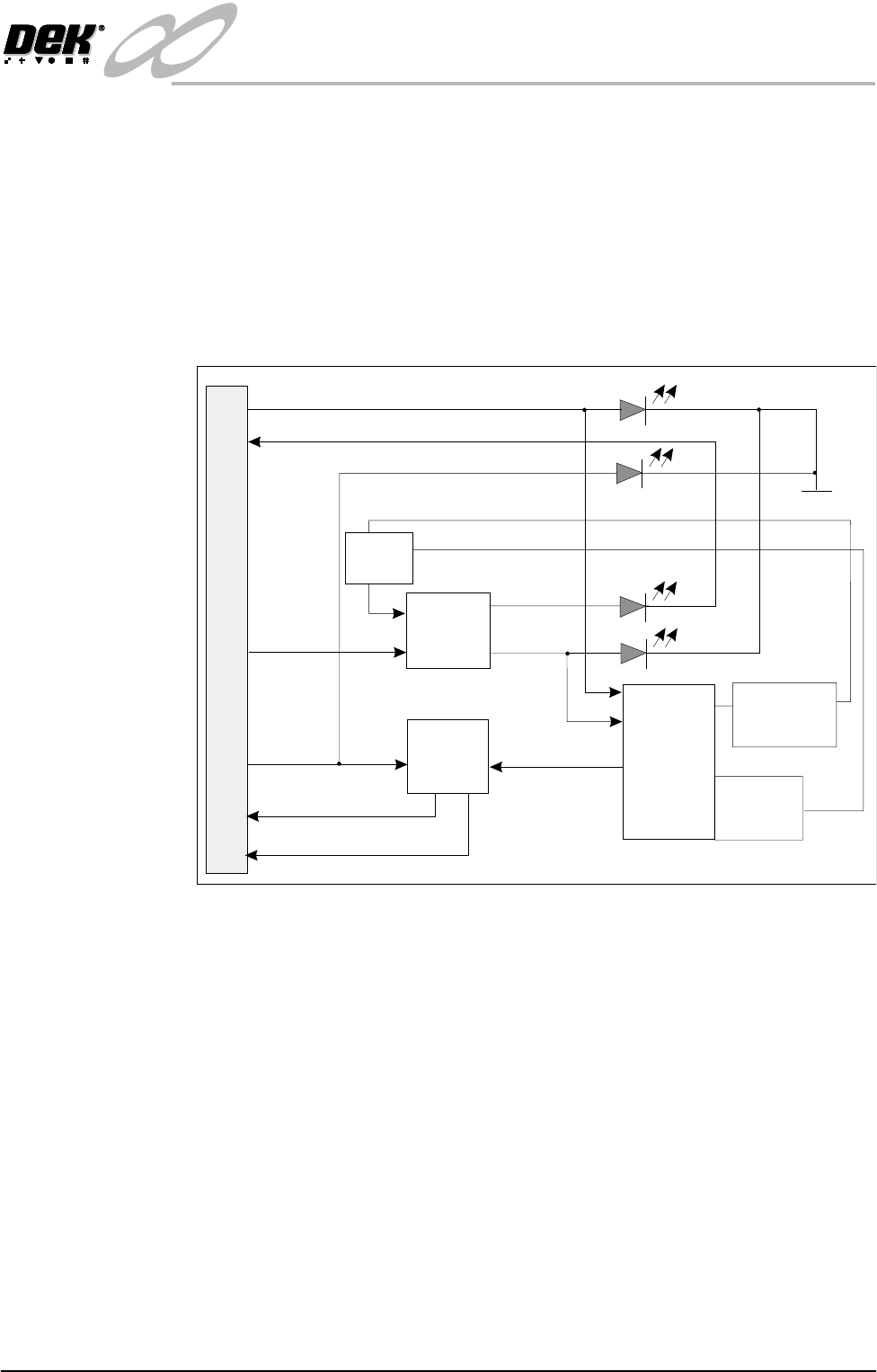
The head lift power driver card provides motor drive to the head lift actuator
enabling the head to be driven up or down.
Two 16A relays on the card switch the motor drive voltage to enable the actuator
to drive the head in both directions. The DIR signal from MultiMove Source 6
(PL20) controls the change-over of the relay contacts by switching the relays on
or off.
When ENABLE from MultiMove Source 7 (PL20) is high, the Darlington pair
output driver device Q3 switches on making motor drive voltage available to the
head lift actuator.
Figure 8-5 Simplified Headlift Actuator Circuit
Error Conditions
Thermal Overload Q3 is thermally linked to RT1 a thermal over temperature trip device, should the
motor current cause a temperature rise to an unacceptable level, RT1 triggers
the gate of the thyristor Q4. This action turns Q3 off.
Current Overload Q1 and associated sense resistors R5, R6, R7, R8 and R10 sense the current
through Q3 and hence the motor. If a condition exists where the acceptable
current level is exceeded, Q1 switches on bringing Q4 on as described for the
thermal overload error condition.
ERROR indication ERROR indication is provided by the circuit associated with Q2 and D4 the red
led. Error indication is an input to the MultiMove backplane (IN8) at SK13A.
Circuit Protection The circuit is protected from the back e.m.f’s of the motor and the relays by D6
and D7 respectively (not shown).
Q2
Error
Monitor
Q1
Over Current
Sense
Q3
Darlington
Po w e r
Driver
RT1
Over Temp.
Protection
DIR
MOTOR +
MOTOR -
ENABLE
Motor O/P
ENABLE
ERROR
ERROR
24V (HL)
SK2
Green
Red
Yellow
Yellow
0V
Polarity
Switching
Relays
Q4
(Gate)