00193361-01.pdf - 第23页
Retrofit Instructions Splice Detection Table Controller S / F 07/2002 Edition 23 : The CA T5 cabl e connec ts the table contr oller to the station computer . Plug the en d which has the net work styl e connector in the b…
Retrofit Instructions Splice Detection Table Controller S / F
07/2002 Edition
22
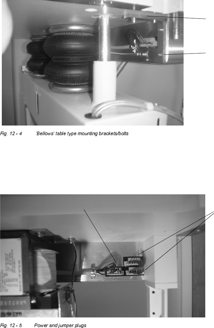
: When retrofitting the ‘bellows’ type feeder table, the mounting method for the controller is two
angle brackets at the back of the controller.
: Attach the new box by removing these four bolts and using the same hardware to attach the
new box (see Fig. 12 - 4).
: Using the orange power jumper plug in the kit, plug this jumper into the plug areas to the right
and above/below each other as shown in Fig. 12 - 5.
: Plug the single existing power cable from the transformer into the single plug area on the left,
and reattach the wire clamp to hold the gray power cable as shown.
Mounting angle
bracket
Mounting bolts
original power plug
power
jumper
plugs
Retrofit Instructions Splice Detection Table Controller S / F
07/2002 Edition
23
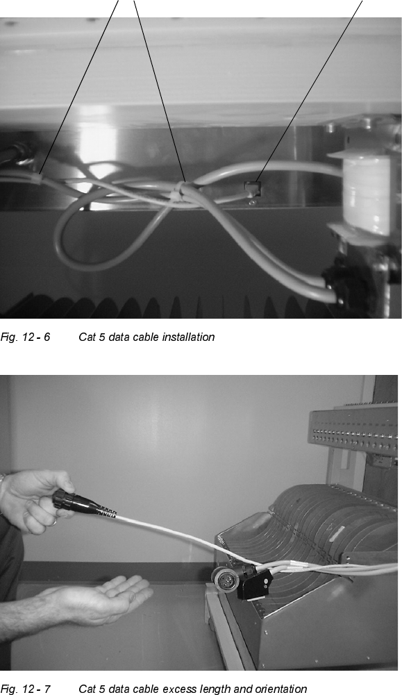
: The CAT5 cable connects the table controller to the station computer. Plug the end which has
the network style connector in the back center of the box as shown in Fig. 12 - 6. Using wire
tiestraps, neatly strap all cables to bundle up under the back of the controller (see Fig. 12 - 6),
and replace the wire ties previously cut on the wire mounting arm. Make sure to leave excess
Cat 5 cable wire length extending towards the front of the feeder table, as shown in Fig. 12 - 7.
Cat 5 data cable plug location
Cable tie straps
Retrofit Instructions Splice Detection Table Controller S / F
07/2002 Edition
24