00193361-01.pdf - 第24页
Retrofit Instructions Splice Detection Table Controller S / F 07/2002 Edition 24
Retrofit Instructions Splice Detection Table Controller S / F
07/2002 Edition
23
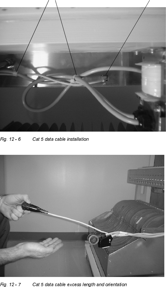
: The CAT5 cable connects the table controller to the station computer. Plug the end which has
the network style connector in the back center of the box as shown in Fig. 12 - 6. Using wire
tiestraps, neatly strap all cables to bundle up under the back of the controller (see Fig. 12 - 6),
and replace the wire ties previously cut on the wire mounting arm. Make sure to leave excess
Cat 5 cable wire length extending towards the front of the feeder table, as shown in Fig. 12 - 7.
Cat 5 data cable plug location
Cable tie straps
Retrofit Instructions Splice Detection Table Controller S / F
07/2002 Edition
24