ENG_SS_108-90807_C.pdf - 第4页
Product specification ‘Multisprin g B signal’ 108 - 9080 7 ............................................................. . ............................................................. ...................................…

Product specification ‘Multispring B signal’ 108-90807
................................................................................................................................................................................................................................................…………………..
Rev. C Page 3 of 7
R1-1 (Rev. 02-00)
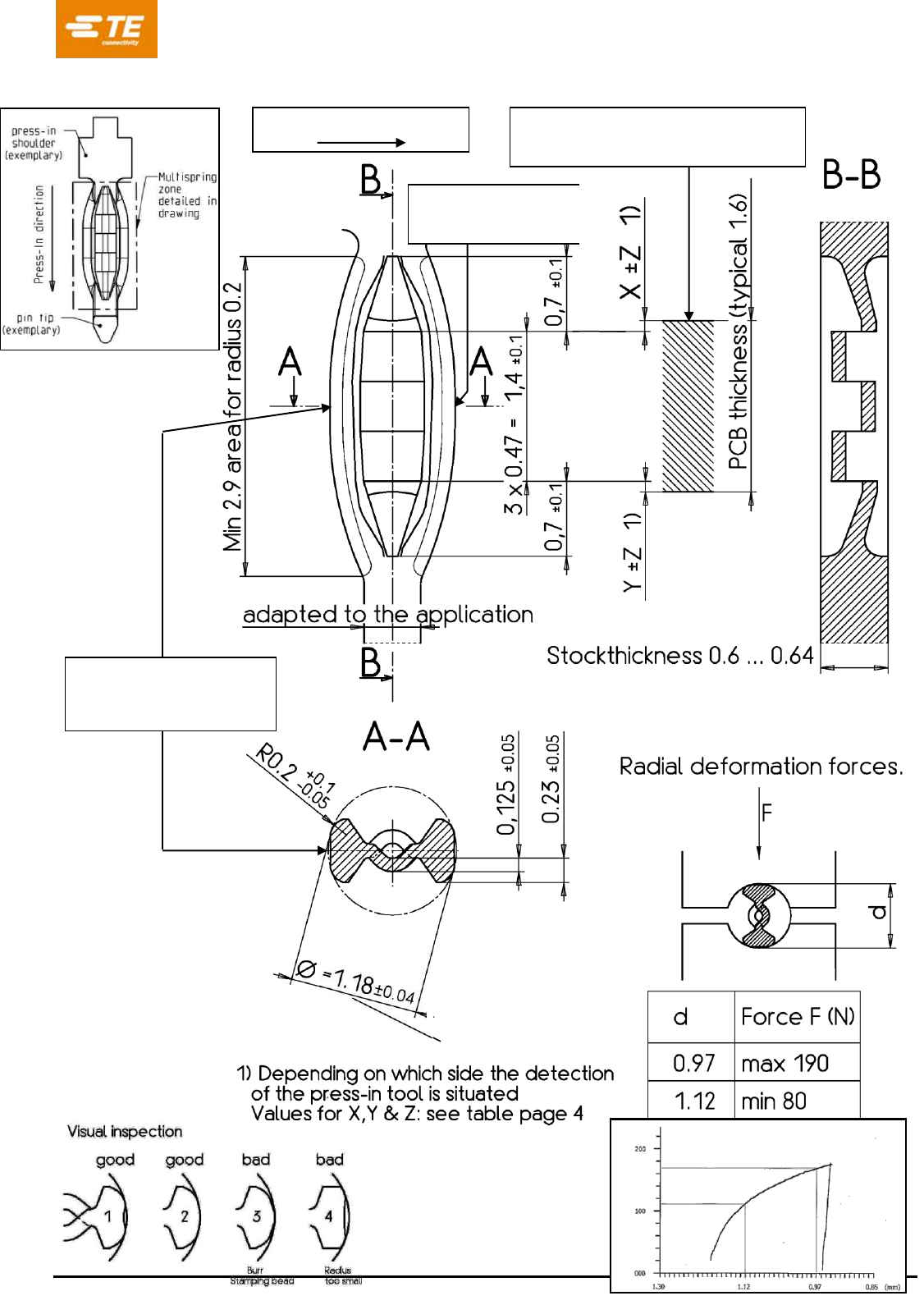
3. PRESS-IN ZONE INFORMATION
Design: see dimensional drawing on page 5
In order not to damage the PTH-hole during the press-in operation, the geometry of the guiding pin
has to be rounded and have a smooth transition to the actual multispring geometry
Stock Material:
Material Type A: CuSn6 C51900
CuSn6 UNS C51900 with tensile strength between 560-650 N/mm²
Material Type B: CuNiSi C19010
CuNiSi UNS C19010 R580s with tensile strength 580-650 N/mm²
Other materials possible after agreement between TE Engineering and the customer
Plating:
- Scenario A old measuring method SnFlash
Meant for airbag applications.
SnFlash measurement according old measuring method (before 03/2019)
0.25-0.52 µm SnPb/Sn over 1.27-2.2µm Ni. Only 1 measuring point (see page 5).
- Scenario B old measuring method SnFlash:
Meant for ABS and non-airbag applications.
SnFlash measurement according old measuring method (before 03/2019)
0.25-0.58 µm Sn over 1.27-2.2 µm Ni. 2 measuring points: (see page 5).
Target should be 0.42 µm Sn
- Scenario C new measuring method SnFlash:
Meant for new applications after 03/2019
SnFlash measurement according the new measuring method (after 03/2019)
Measurement done on 2 measuring points (see page 5)
Thickness measurement based on both sides: 0.45...0.85 μm Sn over 1.27…2.2 μm Ni.
For the first 30 minutes after new start of plating line an increased thickness of 0.45…0.90μm Sn
over 1.27…2.2μm Ni is allowed.
Thickness measurement needs to be done according to Bosch General Measurement instruction 1
279 916 072 and specific Instruction for Sn 1 279 916 073 (TE spec 129-90108).
- Scenario D old measuring method: SnEP:
Not applicable anymore (before 03/2019)
- Scenario E new measuring method: SnEP:
Meant for new applications after 03/2019
0.35 … 0.75 µm SnEP Fa. Enayati GmbH &Co KG (order specification 2 269 915 602 v02) over
1.30 …2.2 µm Ni at functional press fit zone
see drawings page 5 (2 measuring points are same as scenario B old & C new)
The surface thickness measurement of the plating has to be done according to Bosch 1 279 916
072 in general and according to Bosch 1 279 916 074 SnAg / AgSn flash coating specific.
Any temperature treatment after electroplating (for example reflow process) is not allowed without
the agreement of product engineering and customer

Product specification ‘Multispring B signal’ 108-90807
................................................................................................................................................................................................................................................…………………..
Rev. C Page 4 of 7
R1-1 (Rev. 02-00)
General remarks
Measures to reduce Sn-whisker formation have to be checked together with customer.
Measuring points for plating thickness are situated on the functional sides of the Multispring press-fit
zone. See drawing on page 5.
The use of a lubricant on the Multispring zone during the press-in operation can influence the
performance and should therefore be avoided.
Other plating has to be tested on request.
Released combinations of material / plating and PCB parameters:
Multispring B06
108-90807-1
108-90807-2
108-90807-3
108-90807-4
108-90807-5
Material used
CuSn6
C51900
CuSn6
C51900
CuSn6
C51900
CuSn6
C51900
CuNiSi
C19010
Plating
SnFlash old
Scenario B
SnFlash new
Scenario C
SnEP old
Scenario D
Sn EP new
Scenario E
SnEP new
Scenario E
PCB
technology
iSn
iSn
iSn
iSn / OSP
iSn / OSP
Info: Bosch BV
1 279 927 156 02
2 269 915 608 00
1 279 927 405 00
1 039 xxx yyy v00
1 039 926 523 v00
2 269 915 681
4. INFORMATION ON THE APPLICATION.
The Multispring press-fit zone as described, can be used in a
Individual press-in termination.
Straight or right-angle termination.
Rear plug up.
Wrapped connection.
Connector or module with pre-assembled press-in terminations.
Product specification ‘Multispring B signal’ 108-90807
................................................................................................................................................................................................................................................…………………..
Rev. C Page 5 of 7
R1-1 (Rev. 02-00)
Place for clamping (radial force
measurement): X = 0.1 mm
Plating direction of strip
Place to measure
plating thickness (only
scenario B,C&E)
Place to measure
plating thickness
(scenario A,B,C & E)
Short term capability
of minimum 1.67
Radial force