ENG_SS_108-90807_C.pdf - 第5页
Product specification ‘Multisprin g B signal’ 108 - 9080 7 ............................................................. . ............................................................. ...................................…

Product specification ‘Multispring B signal’ 108-90807
................................................................................................................................................................................................................................................…………………..
Rev. C Page 4 of 7
R1-1 (Rev. 02-00)
General remarks
Measures to reduce Sn-whisker formation have to be checked together with customer.
Measuring points for plating thickness are situated on the functional sides of the Multispring press-fit
zone. See drawing on page 5.
The use of a lubricant on the Multispring zone during the press-in operation can influence the
performance and should therefore be avoided.
Other plating has to be tested on request.
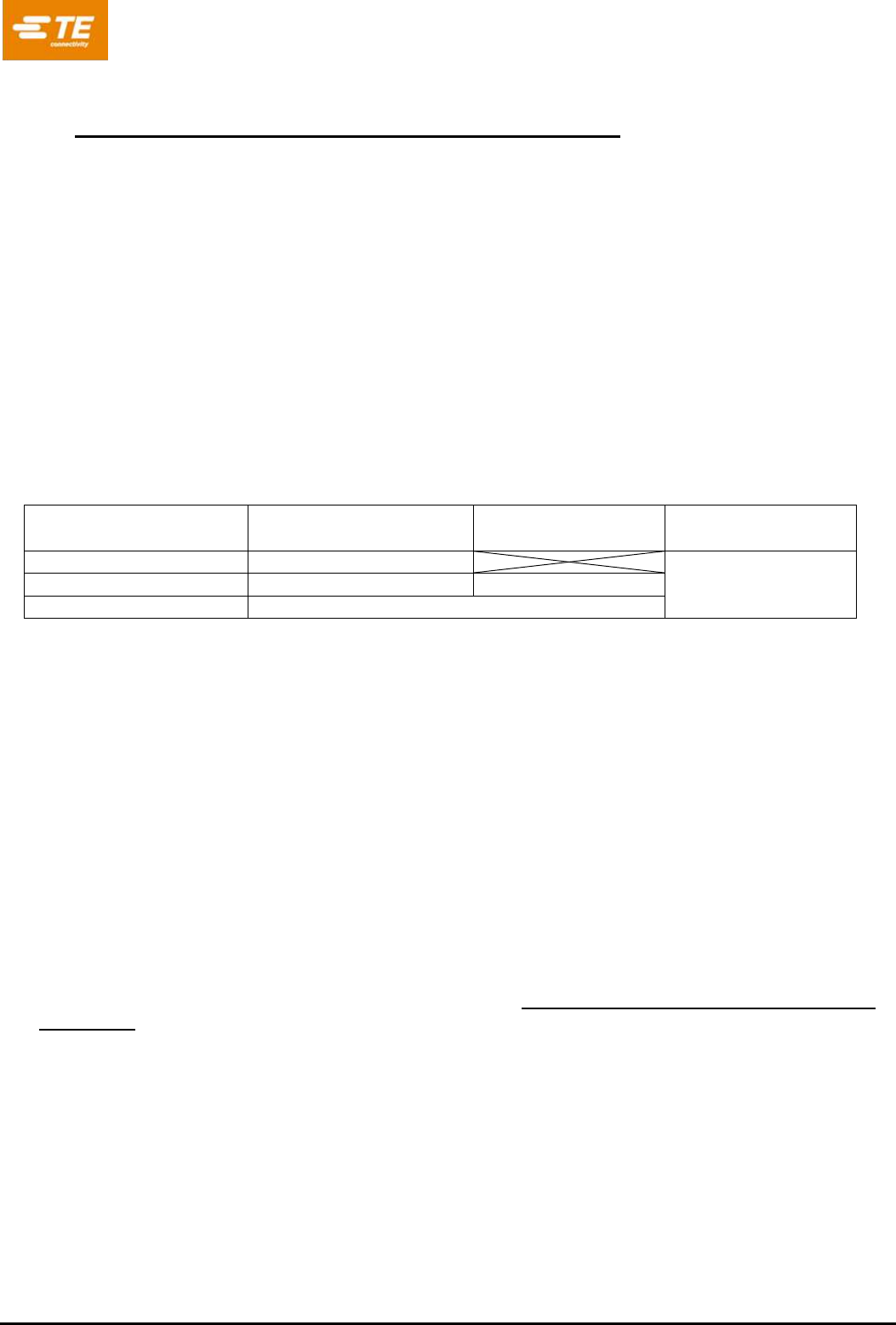
Released combinations of material / plating and PCB parameters:
Multispring B06
108-90807-1
108-90807-2
108-90807-3
108-90807-4
108-90807-5
Material used
CuSn6
C51900
CuSn6
C51900
CuSn6
C51900
CuSn6
C51900
CuNiSi
C19010
Plating
SnFlash old
Scenario B
SnFlash new
Scenario C
SnEP old
Scenario D
Sn EP new
Scenario E
SnEP new
Scenario E
PCB
technology
iSn
iSn
iSn
iSn / OSP
iSn / OSP
Info: Bosch BV
1 279 927 156 02
2 269 915 608 00
1 279 927 405 00
1 039 xxx yyy v00
1 039 926 523 v00
2 269 915 681
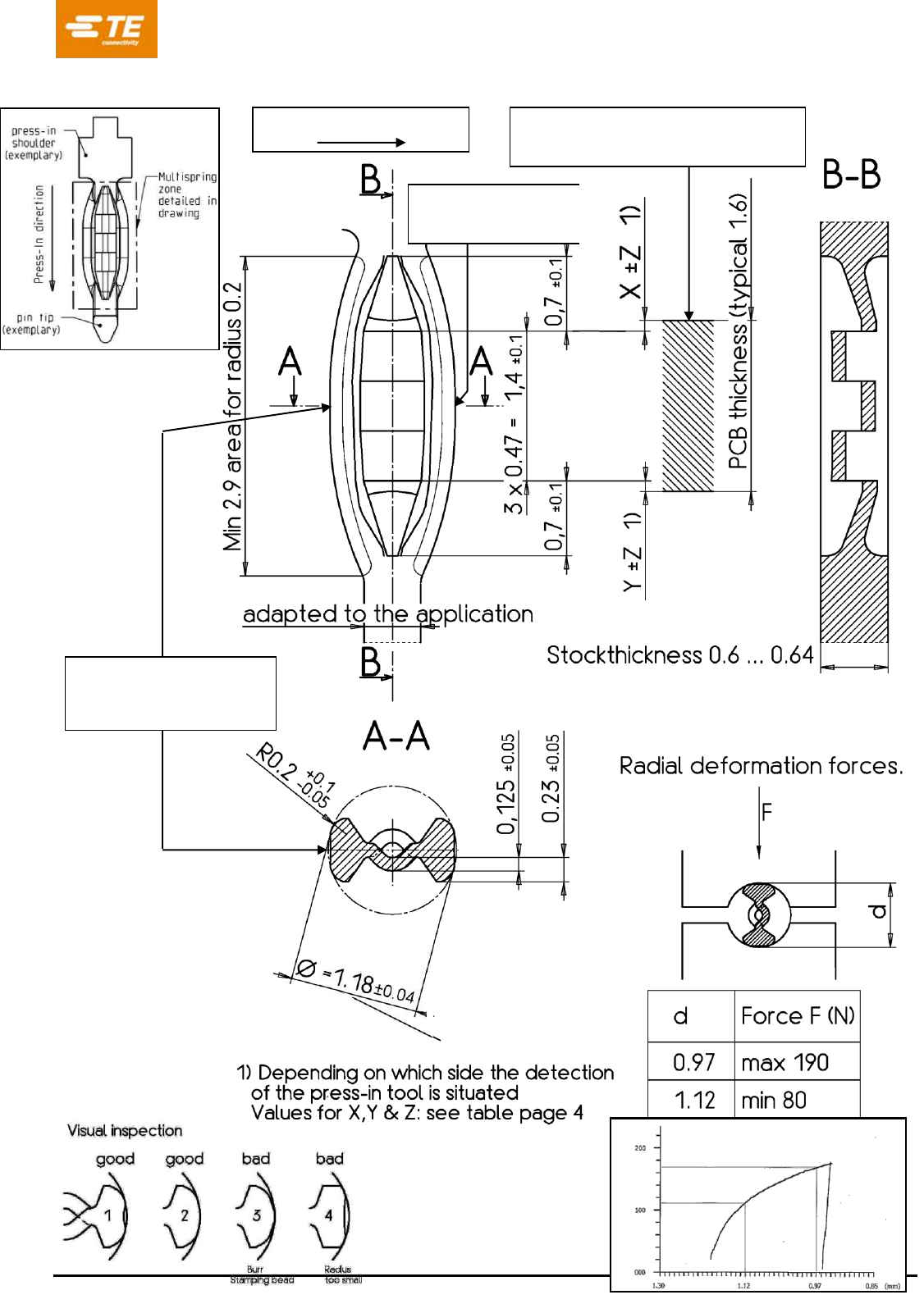
4. INFORMATION ON THE APPLICATION.
The Multispring press-fit zone as described, can be used in a
Individual press-in termination.
Straight or right-angle termination.
Rear plug up.
Wrapped connection.
Connector or module with pre-assembled press-in terminations.
Product specification ‘Multispring B signal’ 108-90807
................................................................................................................................................................................................................................................…………………..
Rev. C Page 5 of 7
R1-1 (Rev. 02-00)
Place for clamping (radial force
measurement): X = 0.1 mm
Plating direction of strip
Place to measure
plating thickness (only
scenario B,C&E)
Place to measure
plating thickness
(scenario A,B,C & E)
Short term capability
of minimum 1.67
Radial force
Product specification ‘Multispring B signal’ 108-90807
................................................................................................................................................................................................................................................…………………..
Rev. C Page 6 of 7
R1-1 (Rev. 02-00)
5. INSTRUCTION AND TOOLS FOR THE PRESS-IN OPERATION.
Replacement with a new press-in termination is for the moment not guaranteed.
Repairs have to be tested on request.
Press-in depth:
See the dimensional drawing on page 5 for the nominal thickness printed board (1.6mm).
The use of thinner printed boards has to be tested.
For thicker printed boards the position of the press-in zone should be preferably
in the upper half of the printed board thickness. See the application drawing and table.
For complex applications with a high number of pins in the same module, the dimension of X±0.2mm
can be interpreted of the mean of all press-in depths. The maximum single press-in depth should
however be within X±0.3mm. For standalone pins as Single Pin Insertion, the depth tolerance of +0.2
mm to -0.2 mm is valid
PCB Thickness
(nominal)
Nominal Press-in
dimension X
Nominal Press-in
dimension Y
Tolerance Press-in
dimension Z
> 1.6 mm
0.1
±0.2
1.5…1.6 mm
0.1
0.1
0.8…1.5 mm *)
Not released
Depending on the detection side of the press-in tooling, dimension X or Y can be used.
*) The use of thinner printed circuit boards has not been tested. The normal granted retention forces
and PCB deformations can deviate from the usual allowed limits when using a thinner PCB. This
should be tested on request if needed.
Press in force / distance should be controlled.
Press-in speed:
Maximum 5mm/s for headers, housings & modules. Maximum 200 mm/s for stitched pins. Other
speeds need to be tested
Tool information:
The press-in tool has to be adapted to the actual application. To ensure an optimal quality of the
applied TE Connectivity products, we recommend the utilization of application equipment from TE
Connectivity.
The latest news and detailed information can be found on http://www.te.com/en/products/application-
tooling.html.
Contact person : siegfried.beck@te.com.