Vat-valve-doc.pdf
Installation, Operating, and Maintenance Instructions Series 02 VAT Vakuumventile AG, CH-9469 Haag , Switzerland Tel ++41 81 771 61 61 Fax ++41 81 771 4 8 30 Email reception@vat.ch http://www.vat.ch M02001EB 2003 - 04 - …
Installation, Operating, and Maintenance Instructions
Series 02
VAT Vakuumventile AG, CH-9469 Haag, Switzerland
Tel ++41 81 771 61 61 Fax ++41 81 771 48 30 Email reception@vat.ch http://www.vat.ch
M02001EB
2003-04-14
1/13
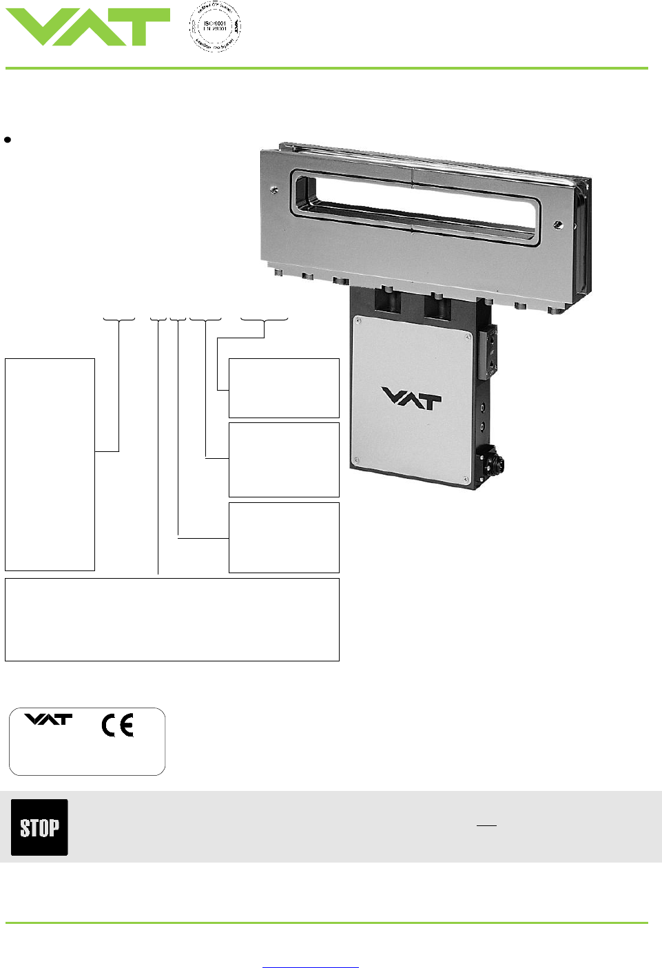
Rectangular Gate Valve MONOVAT
with pneumatic actuator
double acting
The respective product identification is marked on each valve in the following or in a similar way :
made in Switzerland
Fabrication No.:
patented
. .
02 . . . - . . . . - . . . . / . .
A - . . . . . .
Read these «Installation, Operating and Maintenance Instructions» and the enclosed
«General Safety Instructions» carefully before you start any other action.
Actuator:
24 ... w/o solenoid
44 ... with solenoid
Size:
Body material:
A ...
aluminum
E ...
stainless steel
4 character
option code
Flange type:
A
... Same size of opening on seat side and on rear side.
With bonnet flange, gate service via bonnet flange.
gate service via flange
B
... Opening on rear side larger than on seat side.
With bonnet flange, gate service via bonnet flange.
0 2 0 1 0 - B A 2 4 - 0001
09 ... 32 x 222
10 ... 46 x 236
12 ... 50 x 336
01 ... 25 x 160
02 ... 25 x 210
03 ... 25 x 265
04 ... 25 x 420
05 ... 51 x 160
06 ... 51 x 210
07 ... 51 x 265
08 ... 51 x 420
11 ... 46 x 336
0X ... 25 x 254
0X ... 32 x 336

Installation, Operating, and Maintenance Instructions
Series 02
VAT Vakuumventile AG, CH-9469 Haag, Switzerland
Tel ++41 81 771 61 61 Fax ++41 81 771 48 30 Email reception@vat.ch http://www.vat.ch
M02001EB
2003-04-14
2/13
Intended Use of Product
Use product for vacuum applications under the conditions indicated in chapter «Technical data» only! Other applications
are only allowed with the written permission of VAT.
Technical data
Leak rate Body, seat < 1 x 10
-9
mbar l s
-1
Pressure range 1 x 10
-9
mbar to 1.2 bar (abs)
Differential pressure on the gate In either direction 1.2 bar
Max. differential pressure at opening 30 mbar
Cycles until first service 1 million
Bake out temperature Valve body aluminum < 150°C
Valve body stainless steel < 200°C
Pneumatic actuator < 150°C
Standard position indicator < 80°C
Bakeable position indicator < 150°C (optional)
Solenoid < 50°C
Temperature difference body / gate < 40°C
Material Valve body aluminum 3.2315
Valve body stainless steel 1.4435 (AISI 316L)
Gate aluminum 3.2315
Gate stainless steel 1.4435 (AISI 316L)
Bellows end piece 1.4435 (AISI 316L)
Bellows AM 350 (AISI 633)
Bonnet seal VITON®
Gate seal VITON®
Actuation time Opening and closing < 1.5 s
Position indicator contact rating 5 A / 250 V AC, 3 A / 50 V DC
Solenoid See tag on solenoid
Further technical data according to «VAT catalog 2000».
Installation, Operating, and Maintenance Instructions
Series 02
VAT Vakuumventile AG, CH-9469 Haag, Switzerland
Tel ++41 81 771 61 61 Fax ++41 81 771 48 30 Email reception@vat.ch http://www.vat.ch
M02001EB
2003-04-14
3/13
Installation
Leave the blue foil on the valve body openings as long as possible in order to protect the valve interior from dust and
particles. The valve and seals must not be cleaned before installation. The valve is assembled at VAT in a clean
environment and sealed in a plastic bag.
Attach the valve to a clean system only. The screws on the flanges have to be tightened uniformly in crosswise order.
Connect compressed air and electrical power only if
valve is installed into the vacuum system
moving parts cannot be touched
Do not touch electrical parts under voltage.
Admissible forces
The dimensions and tolerances specified on the dimensional drawing must be met under all operating conditions.
Compressed air connection
Compressed air pressure
(min. - max. overpressure) :
4 - 7 bar / 55 - 95 psi
Use only clean, dry or slightly oiled air.
Connections:
internal threads Rp 1/8“ (for USA : 1/8“ NPT)
with solenoid : connection „P“ for air supply
connection „R“ for exhaust
without solenoid : connections „open“ and „closed“
Electrical connection
Sockets for position indicator and solenoid are supplied with the valve. Verify that control voltage matches voltage indicated
on the solenoid.
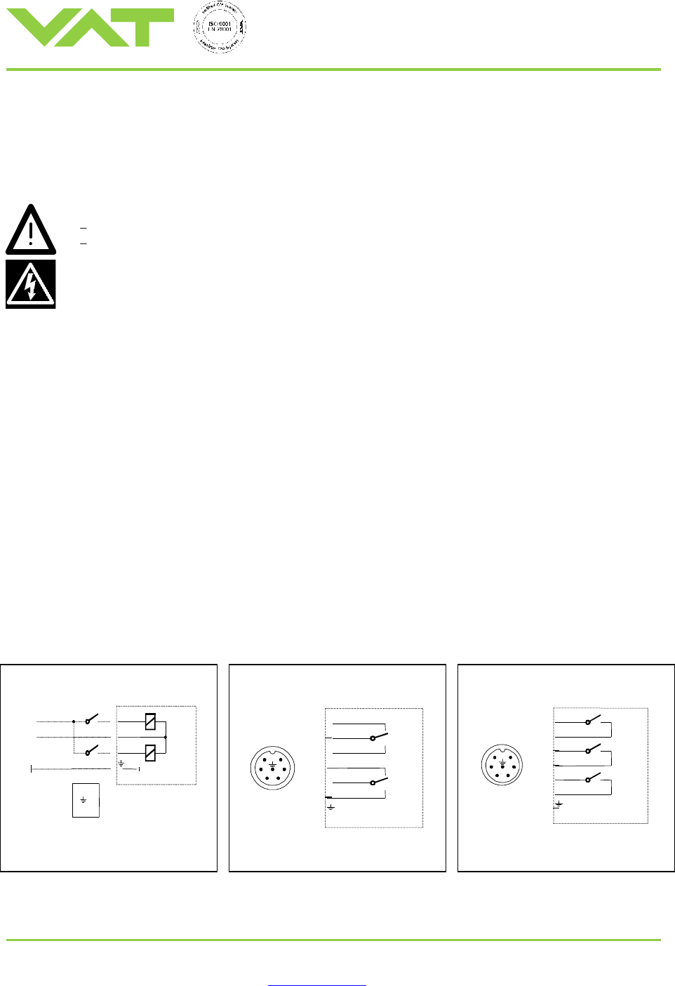
Wiring diagrams :
Solenoid for impulse actuation
Position indicator „open/close“
(Standard)
Position indicator 1xLo / 2xLg
(Optional)
3
MV
power
close
open
1
2
3
1
2
MV = coil of solenoid
Minimum pulse duration : 50 ms
6
5
4
3
2
1
3
1
2
4
6
5
Lo
Lg
Lo = position indicator „open“
Lg = position indicator „close“
Lg2
Lg1
Lo
6
5
4
3
2
1
6
5
4
3
2
1
Lo = position indicator „open“
Lg = position indicator „close“