Vat-valve-doc.pdf - 第6页
Installation, Operating, and Maintenance Instructions Series 02 VAT Vakuumventile AG, CH-9469 Haag , Switzerland Tel ++41 81 771 61 61 Fax ++41 81 771 4 8 30 Email reception@vat.ch http://www.vat.ch M02001EB 2003 - 04 - …
Installation, Operating, and Maintenance Instructions
Series 02
VAT Vakuumventile AG, CH-9469 Haag, Switzerland
Tel ++41 81 771 61 61 Fax ++41 81 771 48 30 Email reception@vat.ch http://www.vat.ch
M02001EB
2003-04-14
5/13
Preventive Maintenance
The italicized numbers refer to the detail drawings in this chapter and to
the drawings in chapter «Spare parts».
Under clean operating conditions, the valve does not
require any maintenance during the specified cycle life
(see chapter «Technical data»).
Preventive maintenance actions include replacing gate,
bellows, and piston seals. Also, the pneumatic parts are
relubricated, and the valve body is cleaned. Other parts
are checked and replaced if necessary. For repair or case
of emergency, VAT recommends to keep at least the
following spare parts on site :
1 MONOVAT gate
2 bellows assembly
1 complete gate/actuator assembly (minimizes MTTR)
Cleaning or Replacing Gate
1. Vent chambers and open valve
2. Disconnect valve from compressed air and electrical supply
3. Unfasten bonnet screws 65 and remove gate/actuator assembly carefully
4. Loosen screws 44 by 1 turn to withdraw gate from shafts
5. Clean or replace gate, reassemble in reverse direction. Tighten gate screws 44 with 5 Nm.
Replacing Bellows
1. Remove gate as described above
2. Remove cover sheets 15 (2x) with screws 47 (4x per sheet)
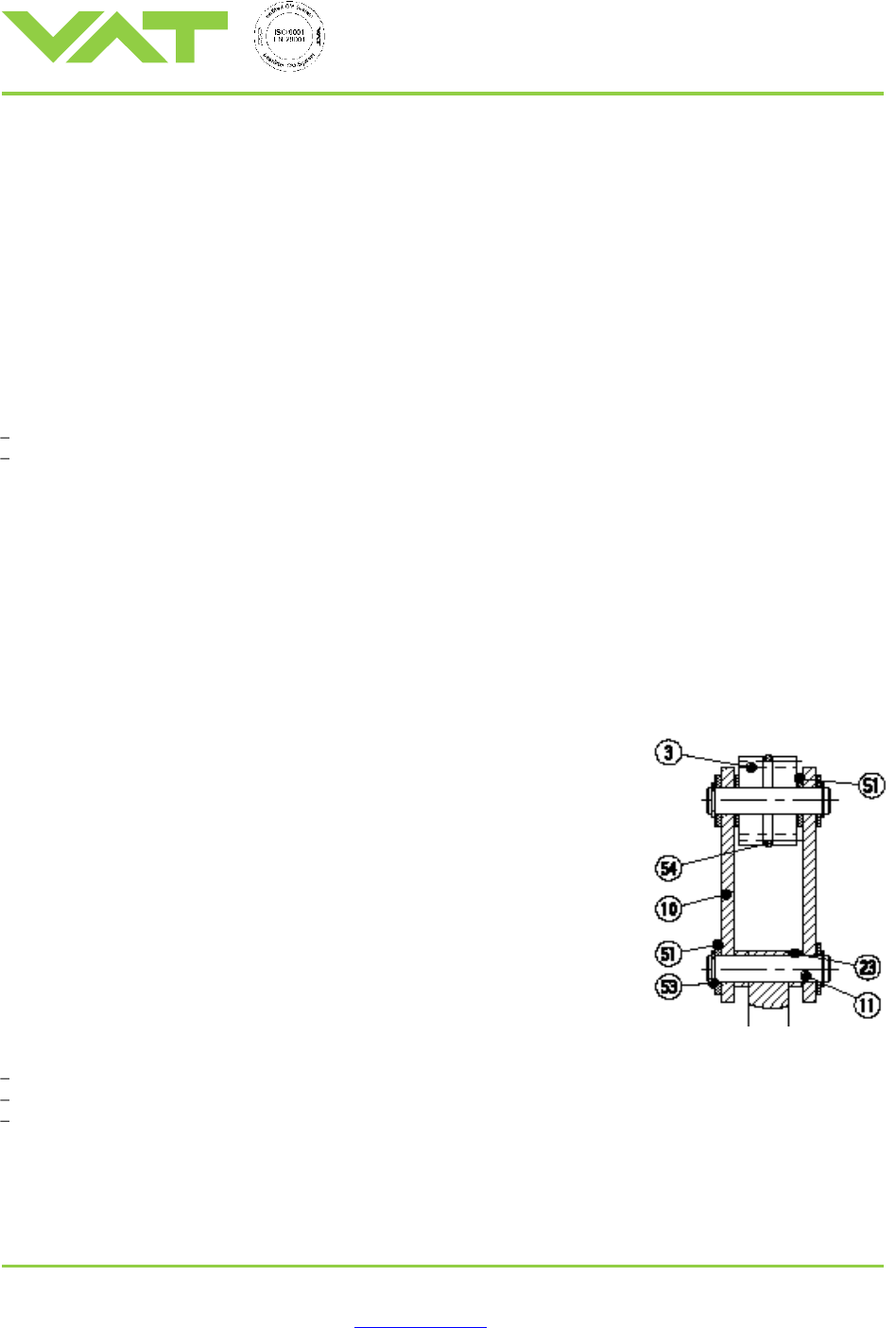
3. Remove circlip 53, washers 51 (2x), distance rings 23 (2x), and bolt 11 (see
detail)
4. Unfasten screws 40 (8x) and remove bonnet 64
5. Pull out bellows assembly 2 carefully
Note : Do not contaminate O-rings 30 and tube 17 with any dirt or lubricant.
6. Mount new bellows assembly 2, O-rings 30 (2x per bellows) and tube 17
(1x per bellows)
Note : Handle new bellows assembly with gloves.
7. Reassemble in reverse direction
Please note :
Do not contaminate the vacuum side of the bellows with any lubricant.
The shaft of replacement bellows assembly is lubricated at the factory for the shaft bushing.
Actuator has a leak detection port (marked on drawing) for the bellows assembly.
Installation, Operating, and Maintenance Instructions
Series 02
VAT Vakuumventile AG, CH-9469 Haag, Switzerland
Tel ++41 81 771 61 61 Fax ++41 81 771 48 30 Email reception@vat.ch http://www.vat.ch
M02001EB
2003-04-14
6/13
Replacing Piston seals:
1. Remove gate and cover sheets as described above
2. Unfasten screws 40 (8x) and remove bonnet 64
3. Remove nut 55 and lug 22, and pull out piston 14 and shaft 13
4. Replace piston O-ring 32 and shaft seal 33, replace static O-rings 31, 35, 36 if damaged
5. Lubricate cylinder and piston with VAT high temperature pneumatic grease
6. Reassemble in reverse direction
Replacing Position indicator
1. Disconnect valve from compressed air and electrical supply
2. Remove cover sheets 15 (2x) with screws 47 (4x per sheet)
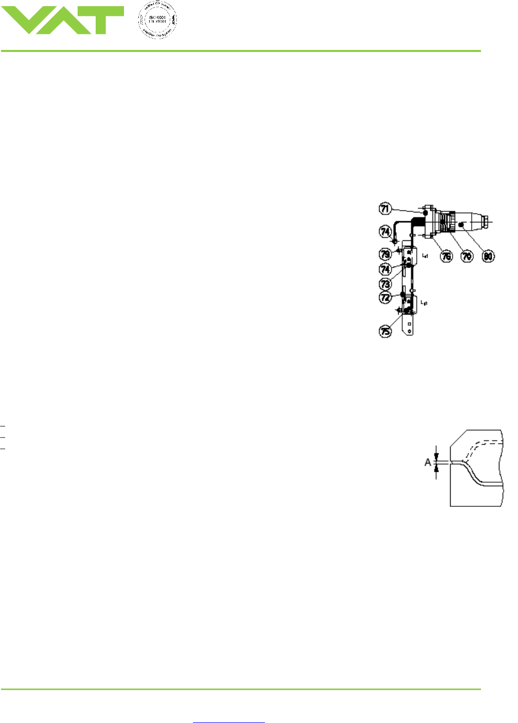
3. Unfasten screws 76 (4x), wire wrap and screws (2x per switch) of micro switch
75, remove plug with wires and switches (see detail)
4. Reassemble in reverse direction
The switch point can be readjusted by loosening the screws of the switch and
moving the switch in the slotted holes of the mounting bar. The switch point should
be set 1 to 1.5 mm prior to the end positions.
Adjustment of Actuator
The compression of the gate seal is adjusted and tested at our factory and must normally not be readjusted.
Verification of Adjustment
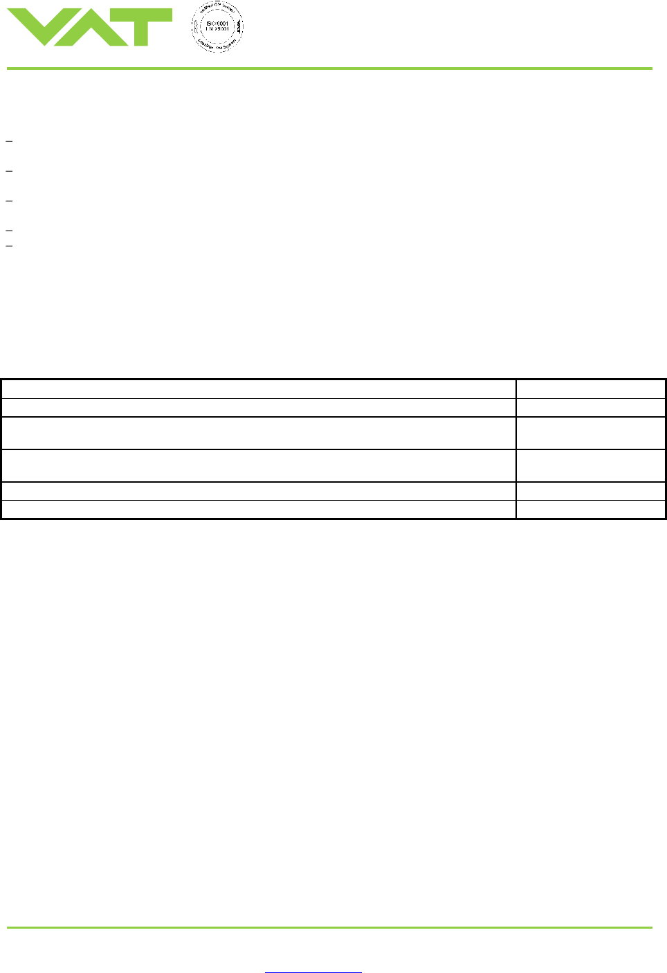
Gap «A» between gate and seat (see sketch beside) should be 3.0 mm ±0.15 mm
Gate and seat should be parallel within 0.2 mm
During closing the mechanical locking should occur between 1.3 and 2 bar air pressure
To check this : 1. Reduce air pressure below 1 bar
2. Command valve in closed position
3. Increase air pressure until a clicking sound indicates the mechanical locking
Adjustment of Compression and / or Parallelism
1. Open valve
2. Loosen screws 43 (2x per rack) of racks 12 (2x)
3. Adjust compression of gate seal by turning both screws 42 by the same angle
Note : Turning screws 42 by 30° results in 0.125 mm change of compression.
4. Adjust parallelism by turning one screw 42
Note : Turning one screw 42 by 30° results in 0.125 mm change of compression on the respective side
5. Fasten screws 43 (4x)
6. Open and close valve, verify again compression and parallelism, repeat adjustment if necessary
Installation, Operating, and Maintenance Instructions
Series 02
VAT Vakuumventile AG, CH-9469 Haag, Switzerland
Tel ++41 81 771 61 61 Fax ++41 81 771 48 30 Email reception@vat.ch http://www.vat.ch
M02001EB
2003-04-14
7/13
Lubrication of Valve
Gaskets in the vacuum area are not lubricated. Small amounts of a suitable high vacuum grease (VAT high
performance vacuum grease) may be used to lubricate O-rings or gate seal.
Lubricate pneumatic cylinder and piston seals with VAT high temperature pneumatic grease. Other lubricants may not
meet our cycle life specification.
Lubricate gears, racks, and lashes in the actuator with Rocol or equivalent.
Lubricate screws outside the vacuum with Molykote 321 R or equivalent. Screws supplied by VAT are lubricated.
Pneumatic cylinder and actuator parts must be relubricated after the specified cycle life (see chapter «Technical data»).
The shaft of new bellows assembly is lubricated at the factory.
Spare Parts
Seal kit, Actuator service kit, Lubricants
Description
Ordering no.
Seal kit, consisting of 1 gate with vulcanized VITON® seal and 1 bonnet seal
D-ordering no. of valve
Actuator service kit for DN 25x... / 32x..., consisting of 2 bellows assemblies, all actuator
seals, and lubricant for piston (VAT high temperature pneumatic grease)
77252-R8
Actuator service kit for DN 46x... - 51x..., consisting of 2 bellows assemblies, all actuator
seals, and lubricant for piston (VAT high temperature pneumatic grease)
77369-R8
VAT high temperature pneumatic grease (for piston), 12g
N-6951-403
VAT high performance vacuum grease, 10g
N-6951-011