Vat-valve-doc.pdf - 第4页
Installation, Operating, and Maintenance Instructions Series 02 VAT Vakuumventile AG, CH-9469 Haag , Switzerland Tel ++41 81 771 61 61 Fax ++41 81 771 4 8 30 Email reception@vat.ch http://www.vat.ch M02001EB 2003 - 04 - …
Installation, Operating, and Maintenance Instructions
Series 02
VAT Vakuumventile AG, CH-9469 Haag, Switzerland
Tel ++41 81 771 61 61 Fax ++41 81 771 48 30 Email reception@vat.ch http://www.vat.ch
M02001EB
2003-04-14
3/13
Installation
Leave the blue foil on the valve body openings as long as possible in order to protect the valve interior from dust and
particles. The valve and seals must not be cleaned before installation. The valve is assembled at VAT in a clean
environment and sealed in a plastic bag.
Attach the valve to a clean system only. The screws on the flanges have to be tightened uniformly in crosswise order.
Connect compressed air and electrical power only if
valve is installed into the vacuum system
moving parts cannot be touched
Do not touch electrical parts under voltage.
Admissible forces
The dimensions and tolerances specified on the dimensional drawing must be met under all operating conditions.
Compressed air connection
Compressed air pressure
(min. - max. overpressure) :
4 - 7 bar / 55 - 95 psi
Use only clean, dry or slightly oiled air.
Connections:
internal threads Rp 1/8“ (for USA : 1/8“ NPT)
with solenoid : connection „P“ for air supply
connection „R“ for exhaust
without solenoid : connections „open“ and „closed“
Electrical connection
Sockets for position indicator and solenoid are supplied with the valve. Verify that control voltage matches voltage indicated
on the solenoid.
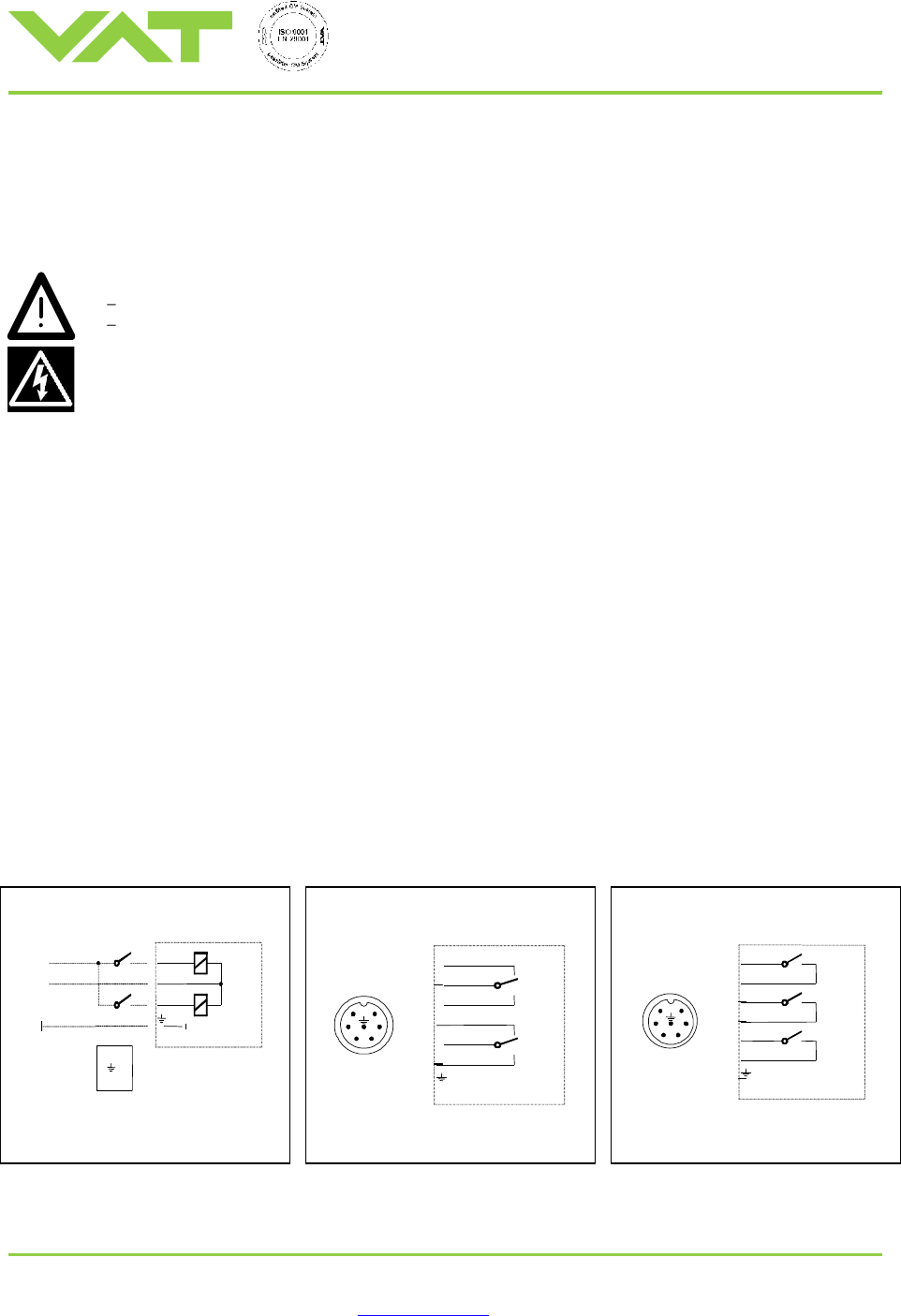
Wiring diagrams :
Solenoid for impulse actuation
Position indicator „open/close“
(Standard)
Position indicator 1xLo / 2xLg
(Optional)
3
MV
power
close
open
1
2
3
1
2
MV = coil of solenoid
Minimum pulse duration : 50 ms
6
5
4
3
2
1
3
1
2
4
6
5
Lo
Lg
Lo = position indicator „open“
Lg = position indicator „close“
Lg2
Lg1
Lo
6
5
4
3
2
1
6
5
4
3
2
1
Lo = position indicator „open“
Lg = position indicator „close“
Installation, Operating, and Maintenance Instructions
Series 02
VAT Vakuumventile AG, CH-9469 Haag, Switzerland
Tel ++41 81 771 61 61 Fax ++41 81 771 48 30 Email reception@vat.ch http://www.vat.ch
M02001EB
2003-04-14
4/13
Operation
Normal operation
Valve with pneumatic actuator : Valve is opened and closed pneumatically.
Admissible temperature
See chapter «Technical data».
Compressed air failure
Valve closed: Valve remains closed (mechanically locked).
Valve open: Valve position is undefined.
Power failure
Valve supplied with pneumatic connection (ordering code 020 . . - . . 24) :
Valve position depends on applied solenoid valve. VAT recommends to operate all transfer valves with impulse actuated
solenoids.
Valve supplied with impulse solenoid (ordering code 020 . . - . . 44) :
Valve closed: Valve remains closed (mechanically locked).
Valve open: Valve remains open.
A started movement will be completed.
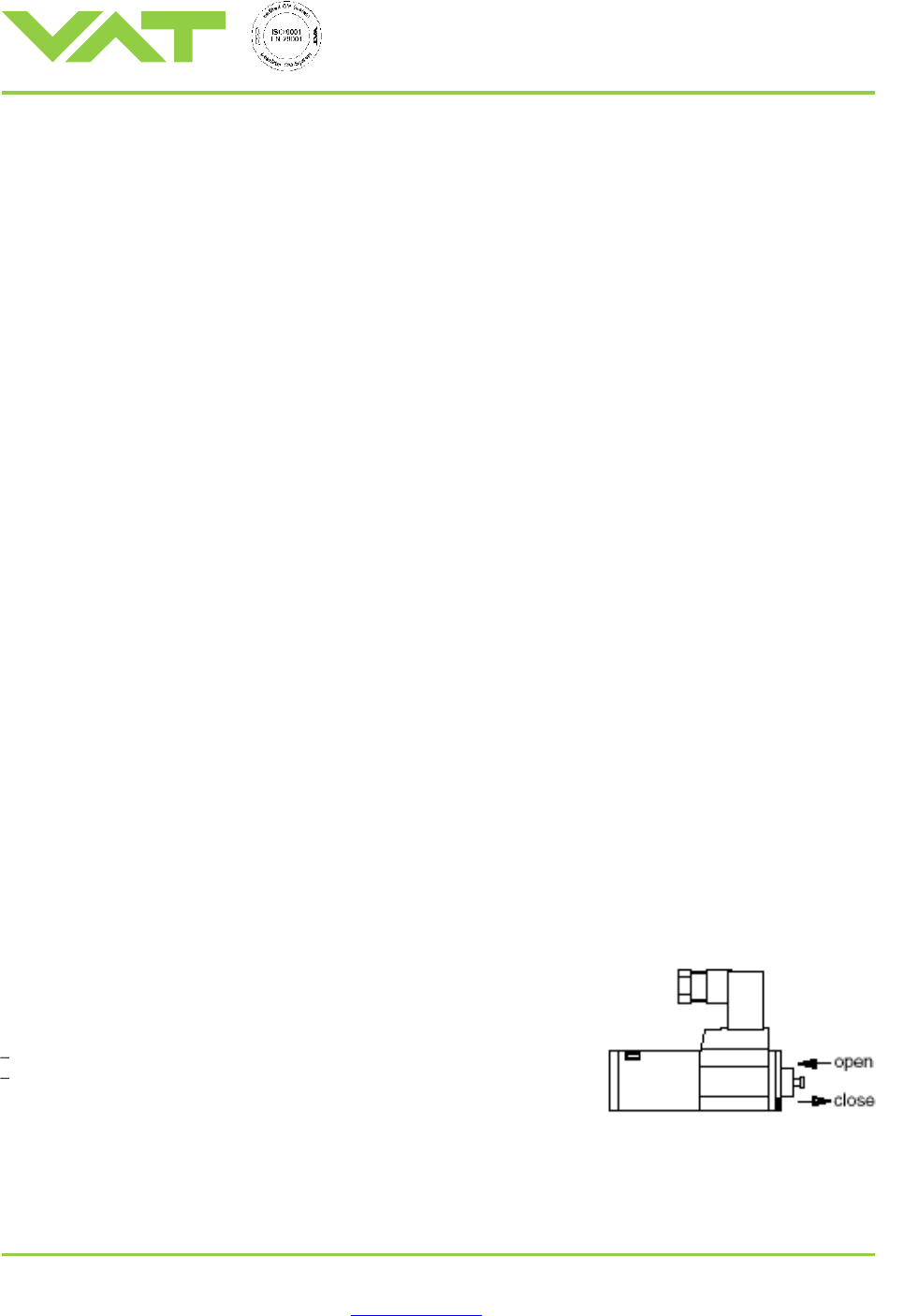
Emergency operation at power failure
In case of power failure, valve can be actuated if compressed air is available.
To actuate valve in case of power failure :
Press push-button : Valve opens
Pull push-button : Valve closes
Installation, Operating, and Maintenance Instructions
Series 02
VAT Vakuumventile AG, CH-9469 Haag, Switzerland
Tel ++41 81 771 61 61 Fax ++41 81 771 48 30 Email reception@vat.ch http://www.vat.ch
M02001EB
2003-04-14
5/13
Preventive Maintenance
The italicized numbers refer to the detail drawings in this chapter and to
the drawings in chapter «Spare parts».
Under clean operating conditions, the valve does not
require any maintenance during the specified cycle life
(see chapter «Technical data»).
Preventive maintenance actions include replacing gate,
bellows, and piston seals. Also, the pneumatic parts are
relubricated, and the valve body is cleaned. Other parts
are checked and replaced if necessary. For repair or case
of emergency, VAT recommends to keep at least the
following spare parts on site :
1 MONOVAT gate
2 bellows assembly
1 complete gate/actuator assembly (minimizes MTTR)
Cleaning or Replacing Gate
1. Vent chambers and open valve
2. Disconnect valve from compressed air and electrical supply
3. Unfasten bonnet screws 65 and remove gate/actuator assembly carefully
4. Loosen screws 44 by 1 turn to withdraw gate from shafts
5. Clean or replace gate, reassemble in reverse direction. Tighten gate screws 44 with 5 Nm.
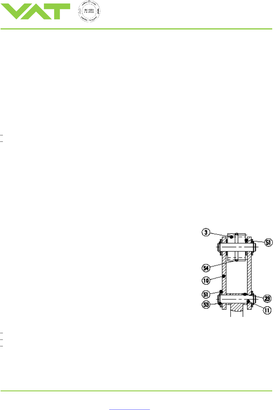
Replacing Bellows
1. Remove gate as described above
2. Remove cover sheets 15 (2x) with screws 47 (4x per sheet)
3. Remove circlip 53, washers 51 (2x), distance rings 23 (2x), and bolt 11 (see
detail)
4. Unfasten screws 40 (8x) and remove bonnet 64
5. Pull out bellows assembly 2 carefully
Note : Do not contaminate O-rings 30 and tube 17 with any dirt or lubricant.
6. Mount new bellows assembly 2, O-rings 30 (2x per bellows) and tube 17
(1x per bellows)
Note : Handle new bellows assembly with gloves.
7. Reassemble in reverse direction
Please note :
Do not contaminate the vacuum side of the bellows with any lubricant.
The shaft of replacement bellows assembly is lubricated at the factory for the shaft bushing.
Actuator has a leak detection port (marked on drawing) for the bellows assembly.