80S-20贴片机.pdf - 第126页
5 Gantries SIPLACE 80S-20/F4/F4-6/F5 Service Manual 5.5 Replacing the Drive Motor of the Y Axis Edition 09/99 5 - 18 5.5 Repla cing the Driv e Motor of the Y A xis 5.5.1 Spare Parts, Auxil iary Materials and Equipment – …

SIPLACE 80S-20/F4/F4-6/F5 Service Manual 5 Gantries
Edition 09/99 5.4 Replacing the Reduction Gear of the X Axis
5 - 17
5.4.3 Installation
● Insert the new endless toothed belt and fit the reduction gear.
● Fit the x-axis cut toothed belt.
● Mount the x-axis drive motor (see Section 5.2.3).
● Tension the endless toothed belt in accordance with Table 5.2 - 1 on page 5 - 11 and the cut toothed belt in
accordance with Table 5.3 - 1 on page 5 - 14
.
● Fit the placement head. After this adjust the placement machine.

5 Gantries SIPLACE 80S-20/F4/F4-6/F5 Service Manual
5.5 Replacing the Drive Motor of the Y Axis Edition 09/99
5 - 18
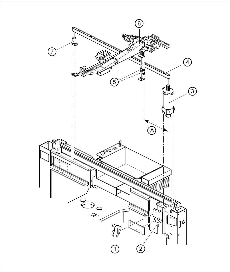
5.5 Replacing the Drive Motor of the YAxis
5.5.1 Spare Parts, Auxiliary Materials and Equipment
– 1 motor for the y axis, complete, from item no. 00318603-01
– Belt tension measuring device, from item no. 00326015-01
5.5.2 Removal
NOTE
You should comply with the safety instructions in Section 1.
● Move the gantry out of the working area to prevent any damage to it.
● Disconnect the components table cable and remove the components table.
● Remove the empty tape cutter by undoing the four mounting screws and disconnect the connection cable.
You will only need to do this with SIPLACE 80S-20 machines.
NOTE
While you are carrying out this work be careful not to damage or dirty the scale and the reading head.
Clean soiled scales as described in the maintenance instructions.
● Remove the stop support together with the stop (applies to F
4
, F
4
-6 and F
5
only).
● Remove the lateral sliding plate holder together with the sliding plate.
● Remove the components table support.
● Loosen the y-belt at the tension rollers using the hexagon socket screw key, size 8.
● Undo the two M6 mounting screws and remove the motor.
● With gantry 1, disconnect the electrical connections of the motor unit. In the case of gantry 2 the electrical
connections are located behind the main switch.
NOTE
The motor is supplied as a complete unit consisting of the motor itself, the tachometer and motor pinion and
for this reason should also be replaced as a complete unit.
SIPLACE 80S-20/F4/F4-6/F5 Service Manual 5 Gantries
Edition 09/99 5.5 Replacing the Drive Motor of the Y Axis
5 - 19
Fig. 5.5.1 Y-motor unit