80S-20贴片机.pdf - 第429页
SIPLACE 80S-20/F4 Service Manual 13 6-Segment Revolver Head (8000) Edition 07/97 13.3 Replacing the Distributor Board and the Components Camera 13 - 15 Fig. 13.3.1 Replacing distributor board and the components camera Ke…

13 6-Segment Revolver Head (8000) SIPLACE 80S-20/F4 Service Manual
13.3 Replacing the Distributor Board and the Components Camera Edition 07/97
13 - 14
13.3 Replacing the Distributor Board and the
Components Camera
13.3.1 Replacing the Distributor Board (Board at the Star Motor)
PLEASE NOTE
This work may only be carried out by Siemens service technicians or by the customer’s appropriately trained
personnel.
Spare parts
Distributor board SP6/12, from item no. 00330648S01
● Disconnect plug-in connections X13 and X14 from head board C0005.
● Undo the hexagon socket screw (M3 x 8).
● Undo the three hexagon spacers M3x7, M3x9 and M3x10 (see Fig. 13.3.1).
● Disconnect plug-in connections X3 to X12 from distributor board Y 0010 (see Fig. 13.3.1).
● Carefully detach the hose from the compressed air sensor.
● When installing, proceed in the reverse sequence of operations.
– No adjustment of settings will be necessary.
13.3.2 Replacing the Components Camera
Spare parts
Components camera 39x39, from item no. 00330600S01
NOTE
The components camera is only replaced as a complete unit.
● Disconnect plug-in connection X3 from board Y0021 (see Fig. 13.3.1).
● Unscrew and remove the four hexagon socket screws (M4x10) and carefully remove the fastening clip of
the Z motor.
● Carefully remove the components camera (see Fig. 13.3.1).
● When re-installing the camera proceed in the reverse sequence of operations.
ATTENTION ∆
!
When you fit the components camera make sure that the stop faces are clean and that the alignment pins are
seated firmly. Then tighten up the screws.
– Please refer to the Sitest instructions for information on the procedure how to adjust the components cam-
era.
SIPLACE 80S-20/F4 Service Manual 13 6-Segment Revolver Head (8000)
Edition 07/97 13.3 Replacing the Distributor Board and the Components Camera
13 - 15
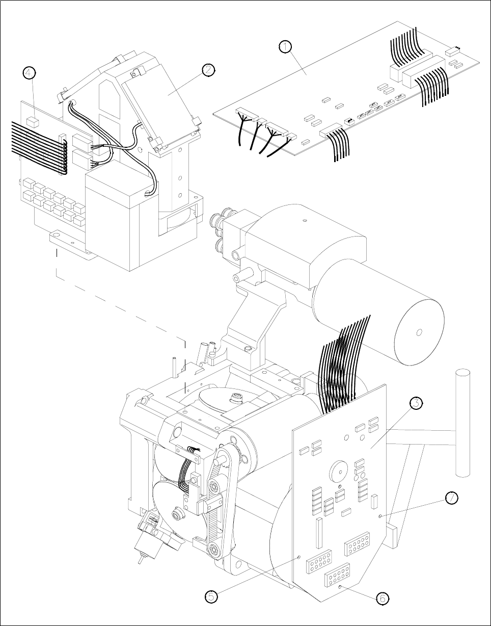
Fig. 13.3.1 Replacing distributor board and the components camera
Key to Fig. 13.3.1
1 Small axis conversion board 5 M3x9 hexagon spacer
2 Component camera 6 M3x10 hexagon spacer
3 Distributor board 7 M3x7 hexagon spacer
4 Y0021 components camera illumination board

13 6-Segment Revolver Head (8000) SIPLACE 80S-20/F4 Service Manual
13.4 Vacuum Generator Block Edition 07/97
13 - 16
13.4 Vacuum Generator Block
13.4.1 Replacing the Venturi Nozzles and the O-Ring
Spare parts
Vacuum nozzle, 1.5 dia. (holding circuit) from item no. 00319420S02
O-ring 14 x 1.5 NBR 70B (holding circuit) from item no. 00320048S01
Vacuum nozzle (placement circuit) from item no. 00319423S02
O-ring 10 x 1.5, NBR 70B (placement circuit) from item no. 00320047S01
● Disconnect the compressed air lines from the vacuum generator.
● Undo the two hexagon socket screws (M3 x 22) and remove the distributor.
● Carefully remove the two venturi nozzles together with their o-rings (see Fig. 13.4.1).
● Replace or clean the parts as appropriate.
● Before fitting the o-rings, lightly grease them with Unisilkon.
● To re-install, proceed in the reverse sequence of operations.
NOTE
When inserting the venturi nozzles make sure that the o-rings are seated firmly in the cutouts.
13.4.2 Replacing the Silencer
Spare parts
Silencer, from item no. 00320964-01
● Detach the silencer by hand by turning it anticlockwise.
● Pull out the threaded rod and remove the funnel from the silencer (see Fig. 13.4.1).
● Replace the silencer with a new one.
● When installing, proceed in the reverse sequence of operations.