00194798-01.pdf - 第11页
Installation Manual, Station Software Version 602.01 Edition 06/2006 11 of 60 Machine type Subsystem BIOS / application Version File name X2 X3 X4 D3 D4 BIOS 03.04 03.04 T0500304.hex T0600304.hex X X X X X PCB convey or …

Installation Manual, Station Software Version 602.01 Edition 06/2006
10 of 60
Machine type
Subsystem BIOS / application Version File name
X2 X3 X4 D3 D4
BIOS
02.00
03.3E
A0300200.bhx
A040033E.bhx
X
X
X
X
X
X
Application 1
02.08
01.06
A0310208.bhx
A0410106.bhx
X
X
X
X
X
X
Application 2 / star
02.45
04.4D
C0320245.bhx
C042044D.bhx
X
X
X
X
X
X
Application 2 / Z
02.45
04.4D
W0320245.bhx
W042044D.bhx
X
X
X
X
X
X
BIOS / DP
01.03
01.03
J0300103.hex
J0400103.hex
X
X
X
X
X
X
C&P20 head axes
Application 1 / DP
01.16
01.16
J0310116.hex
J0410116.hex
X
X
X
X
X
X
Machine type
Subsystem BIOS / application Version File name
X2 X3 X4 D3 D4
BIOS
3.CF
3.CF
K06003CF.bhx
K07003CF.bhx
X
X
X
X
X
RV head (modular)
Application 1
1.16
0.29
K0610116.bhx
K0710029.bhx
X X X X
X
BIOS 03.CF I03003CF.bhx X X X
Twin Head head
functions
Application 1 02.07 I0310207.bhx X X X
BIOS
03.CF H01003CF.bhx
X X X
C&P20 head
Application 1
01.3E H011013E.bhx
X X X
BIOS
02.01
01.01
02.01
02.00
B0100201.HEX
B0200101.hex
B0400201.bhx
B0500200.bhx
X
X
X
X
X
X
X
X
X
X
X
Component table
Application 1
04.03
01.07
03.03
04.07
B0110403.hex
B0210107.hex
B0410303.bhx
B0510407.bhx
X
X
X
X
X
X
X
X
X
X
X
BIOS
01.00
02.01
G0200100.hex
G0100201.hex
X X X X
X
Tape cutter
Application 1
01.00
03.02
G0210100.hex
G0110302.hex
X X X X
X

Installation Manual, Station Software Version 602.01 Edition 06/2006
11 of 60
Machine type
Subsystem BIOS / application Version File name
X2 X3 X4 D3 D4
BIOS
03.04
03.04
T0500304.hex
T0600304.hex
X
X
X
X
X
PCB conveyor
Application 1
06.07
06.07
T0510607.hex
T0610607.hex
X
X
X
X
X
BIOS
03.24
03.24
E0100324.bhx
E0200324.bhx
X X X X
X
Main /
Subdistributor
Application 1
03.55
04.01
E0110355.bhx
E0210401.bhx
X X X X
X
BIOS
03.CF
V05003CF.bhx X X X X X
VISION modules
Application 1
03.02
V0510302.bhx X X X X X
BIOS
02.00
M0200200.bhx X X X
MTC 2
Application 1
02.05
M0210205.bhx
X X X
BIOS
02.04
03.04
L0200204.hex
L0300204.hex
X
X
X
X
X
X
Digital pressure
regulation valve
C&P20 head
Application 1
02.06
03.06
L0210306.hex
L0310306.hex
X
X
X
X
X
X
BIOS
01.01
UA100101.hex X X X
X-Feeder
Application 1
01.25
UA110125.hex X X X
The hardware status of a subsystem is identified by the 3rd digit in the file name.
The example below shows the file name of the BIOS for the main axes of the X-Series:
File name Hardware status
A0
300200.bhx A 363
A0
400309.bhx A 364
Installation Manual, Station Software Version 602.01 Edition 06/2006
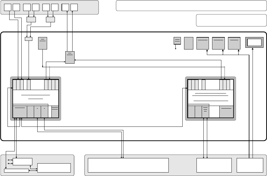
3.2 SIPLACE X series hardware components
The following diagram shows the hardware components of the computer system for the X-series machine
types:
Camera system for 2 processing areas with 2 - 4 placement heads
(C&P20/RV head and/or Twin Head) with component vision and PCB position
recognition and up to 2 x complanarity sensor option
(interfaces: sensor > RS485 > USB)
PS
Power supply
Computer unit
Fan unit
40 GB
HD
Manual MUX
switching only
used
(video data
(stationary
images) via hub)
CD ROM drive to
be connected
with the required
computer by
reconnecting the
USB cable
CPU07x-
ZUBLPT
Possibly VMP-HF version with only 1 x VGA
input and 2 x VGA outputs (connect 1 VGA
cable to one of the 2 computers)
PS DC-DC
+-12V / 6A
KSP SV501
PS DC-DC
+3.3V / 20A
KSP NTS50-3
PS DC-DC
+5.0V / 60A
KSP NTS50-5
+24 V
+52 V
Production line
LAN (hub)
Customer LAN
1 2
CAN bus
Decentralized controller
Machine
Y cable
Touch
screen 1
User
interface
Keyboard Y
adapter
Mouse Y
adapter
Video
Multi-
plexer
Touch
screen 2
Keyboard
1
Keyboard
2
Mouse
1
Mouse
2
Monitor
1
Monitor
2
Structure of the computer unit with its interfaces
SIPLACE Pro
programming system
Programming system
and external networks
LAN
Possibly switch
control elements
to USB port
P M 1.6 GHz, ASP 768 MB
Station computer
SMP16-CPU086
+3.6V
Buffer
battery
to
CPUs
Bay
R
E
S
E
R
V
E
SIPLACE X2/X3/X4/D3
series / software: PF IIplus / 2-computer mode
C P C I B u s
LAN HUB .
1 2 1 2 3 4
KSP COM 294
Hot-
link
?
Hot-
link
?
R
E
S
E
R
V
E
CD
KSP
MEM365
L
A
N
C
O
M
A
C
O
M
B
V
G
A
U
S
B
1
U
S
B
2
K
E
Y
B
U
S
B
3
KSP
VMP-HF
40 GB
HD FD
CPCI-MEM371
C P C I B u s
Celeron 650 MHz, ASP 128 MB
Machine controller
SMP16-CPU076 (previous configuration)
CAN
1 2
CPCI-
COM
168
R
E
S
E
R
V
E
R
E
S
E
R
V
E
L
A
N
C
O
M
A
C
O
M
B
V
G
A
U
S
B
1
U
S
B
2
K
E
Y
B
Intel M 1600 MHz, RAM 256 MB
SMP16-CPU086 (current configuration)
Fig. 3-1: Hardware components of the computer system for the SIPLACE X series and the SIPLACE D3
12 of 60