00194798-01.pdf - 第13页
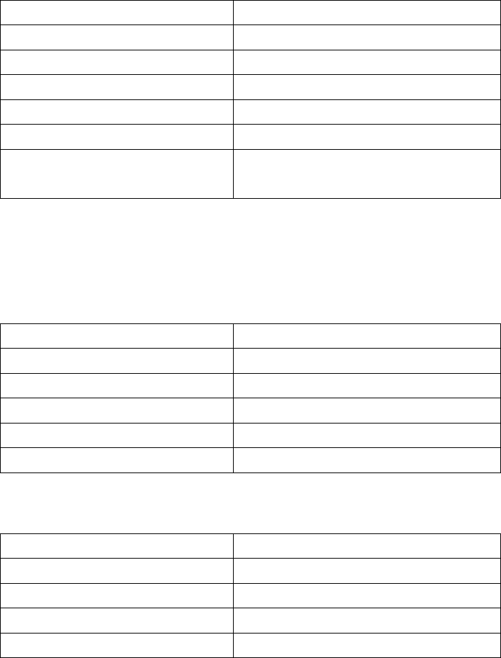
Installation Manual, Station Software Version 602.01 Edition 06/2006 13 of 60 3.2.1 Station computer Name SMP16-CPU086 CPU / clock frequency P M / 1.6 GHz RAM 768 MB Hard disk 40 GB CD ROM drive Yes Serial interfaces 2 N…
Installation Manual, Station Software Version 602.01 Edition 06/2006
3.2 SIPLACE X series hardware components
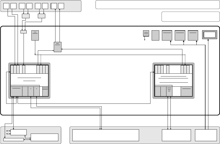
The following diagram shows the hardware components of the computer system for the X-series machine
types:
Camera system for 2 processing areas with 2 - 4 placement heads
(C&P20/RV head and/or Twin Head) with component vision and PCB position
recognition and up to 2 x complanarity sensor option
(interfaces: sensor > RS485 > USB)
PS
Power supply
Computer unit
Fan unit
40 GB
HD
Manual MUX
switching only
used
(video data
(stationary
images) via hub)
CD ROM drive to
be connected
with the required
computer by
reconnecting the
USB cable
CPU07x-
ZUBLPT
Possibly VMP-HF version with only 1 x VGA
input and 2 x VGA outputs (connect 1 VGA
cable to one of the 2 computers)
PS DC-DC
+-12V / 6A
KSP SV501
PS DC-DC
+3.3V / 20A
KSP NTS50-3
PS DC-DC
+5.0V / 60A
KSP NTS50-5
+24 V
+52 V
Production line
LAN (hub)
Customer LAN
1 2
CAN bus
Decentralized controller
Machine
Y cable
Touch
screen 1
User
interface
Keyboard Y
adapter
Mouse Y
adapter
Video
Multi-
plexer
Touch
screen 2
Keyboard
1
Keyboard
2
Mouse
1
Mouse
2
Monitor
1
Monitor
2
Structure of the computer unit with its interfaces
SIPLACE Pro
programming system
Programming system
and external networks
LAN
Possibly switch
control elements
to USB port
P M 1.6 GHz, ASP 768 MB
Station computer
SMP16-CPU086
+3.6V
Buffer
battery
to
CPUs
Bay
R
E
S
E
R
V
E
SIPLACE X2/X3/X4/D3
series / software: PF IIplus / 2-computer mode
C P C I B u s
LAN HUB .
1 2 1 2 3 4
KSP COM 294
Hot-
link
?
Hot-
link
?
R
E
S
E
R
V
E
CD
KSP
MEM365
L
A
N
C
O
M
A
C
O
M
B
V
G
A
U
S
B
1
U
S
B
2
K
E
Y
B
U
S
B
3
KSP
VMP-HF
40 GB
HD FD
CPCI-MEM371
C P C I B u s
Celeron 650 MHz, ASP 128 MB
Machine controller
SMP16-CPU076 (previous configuration)
CAN
1 2
CPCI-
COM
168
R
E
S
E
R
V
E
R
E
S
E
R
V
E
L
A
N
C
O
M
A
C
O
M
B
V
G
A
U
S
B
1
U
S
B
2
K
E
Y
B
Intel M 1600 MHz, RAM 256 MB
SMP16-CPU086 (current configuration)
Fig. 3-1: Hardware components of the computer system for the SIPLACE X series and the SIPLACE D3
12 of 60
Installation Manual, Station Software Version 602.01 Edition 06/2006
13 of 60
3.2.1 Station computer
Name SMP16-CPU086
CPU / clock frequency P M / 1.6 GHz
RAM 768 MB
Hard disk 40 GB
CD ROM drive Yes
Serial interfaces 2
Network 1 x 10/100Base-T
2 x 10Base-T
6-port hub
Table 3-1: Station computer hardware (SIPLACE X series and SIPLACE D3)
3.2.2 Machine controller
Name
SMP16-CPU076
CPU / clock frequency
Celeron / 650 MHz
RAM
128 MB
Hard disk
40 GB
Disk drive
3.5", 1.44 MB
Network
1 x 10/100Base-T
Table 3-2: Machine controller hardware (previous configuration of X series)
Name
SMP16-CPU086
CPU / clock frequency
Intel M / 1600 MHz
RAM
512 MB
Hard disk
40 GB
Network
1 x 10/100Base-T
Table 3-3: Machine controller hardware (current configuration of SIPLACE X series and SIPLACE D3)
Installation Manual, Station Software Version 602.01 Edition 06/2006
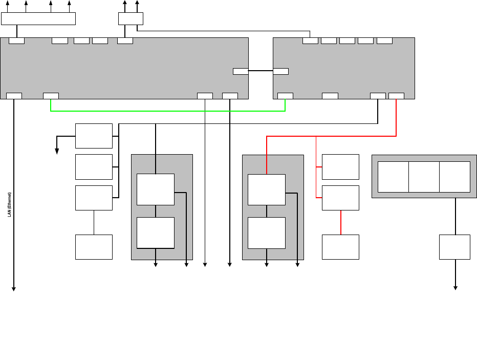
3.3 SIPLACE D4 hardware components
The following diagram shows the hardware components of the computer system for the machine type D4
of the D series:
Structure of the computer unit with its interfaces
Machine type SIPLACE D4
LAN connection
Main switch
Line filter
Power connection
Power connection
Voltages
Protection
circuits
Fuses
Measuring systems
Power supply
Station computer
BoxPC 627V1
Pentium M760 2.0 GHz, 1 GByte RAM, 40 GB HD, CD
2 x 100 MBit LAN, graphics adapter, 4 x USB, 1 x serial, 2 PCI slots
PCI 1: 1st hotlink
PCI 2: 2nd hotlink
LAN
VGA
Cameras
( 4 x component camera,
4 x PCB camera )
Measuring systems
Servo amplifiers
4 x X/Y
8 x head
Axis unit 2
USB1
VideoMux
Motors
Axes
( 3 x A364 )
12 axes
Servo amplifiers
4 x X/Y
8 x head
USB2 USB3 USB4
Hotlink Hotlink
Machine controller
MicroBox 420V2
Pentium III, 933 MHz, 256 MByte RAM, 40 GB HD
2 x 100 MBit LAN, graphics adapter,
4 x USB, 1x serial, 3 x PC104
1st PC104: CAN bus ( 2x )
CAN 1
VGA
LAN 1
USB1
14 of 60
CAN 2
USB2
COM1
USB3 USB4
LAN 2
Motors
Processing area 1 Processing area 2
Monitor
1 2
Keyboard / Touchscreen
1 2
1 MBit/s
500 kBit/s
1 MBit/s
500 kBit/s
Axis unit 1
100 MBit/s
LAN
USB hub
COM1
Conveyor controller
PCB barcode
Gantries
Heads
1 / 2
Gantries
Heads
2 / 4
Axes
( 3 x A364 )
12 axes
I/O module 1 I/O module 2
Component tables 1
/ 4
Tape cutters 1 / 4
Component tables 2
/ 3
Tape cutters 2 / 3
Fig. 3-2: Hardware components of the computer system for the SIPLACE D4