00193363-03.pdf - 第16页
1 Montageanleitung Spleißstellen-Erkennung Basispaket SI PLACE H S-50 Spleißstellenerkennung Basis-Paket HS-50 Ausgabe 03/2008 16
Spleißstellenerkennung Basis-Paket HS-50 1 Montageanleitung Spleißstellen-Erkennung Basispaket SIPLACE HS-50
Ausgabe 03/2008
15
1
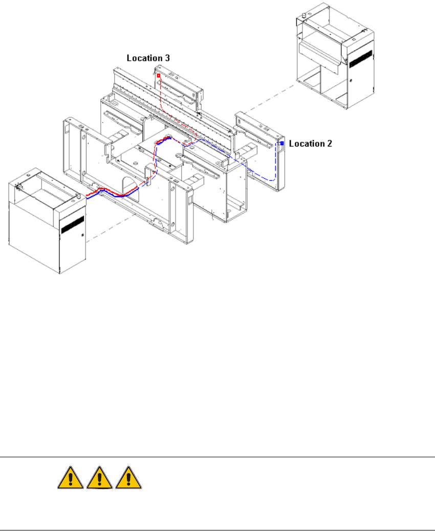
Abb. 1.12 - 8 Verlegung der Kabel von Stellplatz 2 und 3
1
: Verbinden Sie nun die CAT5 Kabel mit der HUB Einheit:
– das Kabel vom Stellplatz 1 mit Buchse Tisch 1 am HUB
– das Kabel vom Stellplatz 2 mit Buchse Tisch 2 am HUB
– das Kabel vom Stellplatz 3 mit Buchse Tisch 3 am HUB
– das Kabel vom Stellplatz 4 mit Buchse Tisch 4 am HUB.
GEFAHR
Der Bestückautomat darf erst eingeschaltet werden, nachdem der HUB metallisch leitend mit dem
Maschinenständer verbunden und verschraubt ist! 1
: Schalten Sie den Bestückautomaten am Hauptschalter wieder ein.
1
1 Montageanleitung Spleißstellen-Erkennung Basispaket SIPLACE HS-50 Spleißstellenerkennung Basis-Paket HS-50
Ausgabe 03/2008
16
Splice Detection Basic Package HS-50 2 Assembly instructions Splice Detection Basic Package SIPLACE HS-50
03/2008 Edition
17
2 Assembly instructions
Splice Detection Basic Package
SIPLACE HS-50
2.1 Overview
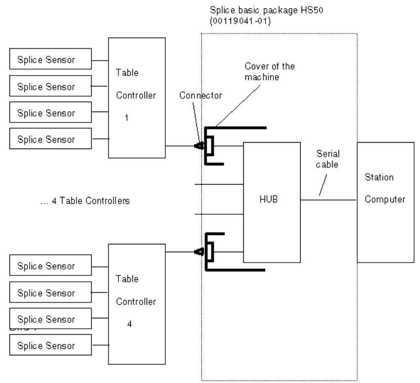
The basic splice detection package provides a link between the changeover tables, their commu-
nication units and splice sensors and the machine’s station computer. The basic package contains
all the components needed to prepare the HS50 for splice detection. 2
You will also have to upgrade each component changeover table with a retrofit kit. 2
2
Abb. 2.10 - 1 Structure of splice detection
Splice Detection Basis Package HS50:
00116936-01
"Splice Detection Station Package HS"
00119032-01
"Splice Detection Table
controller HS/D4"