00193363-03.pdf - 第18页
2 Assembly instructions Splice De tection Basic Package SIPLACE HS-50 Sp lice Detection Basic Package HS-50 03/2008 Edition 18 2.2 Safety Instructions 2 DA N G ER All the work describe d below must only be carr ied out b…
Splice Detection Basic Package HS-50 2 Assembly instructions Splice Detection Basic Package SIPLACE HS-50
03/2008 Edition
17
2 Assembly instructions
Splice Detection Basic Package
SIPLACE HS-50
2.1 Overview
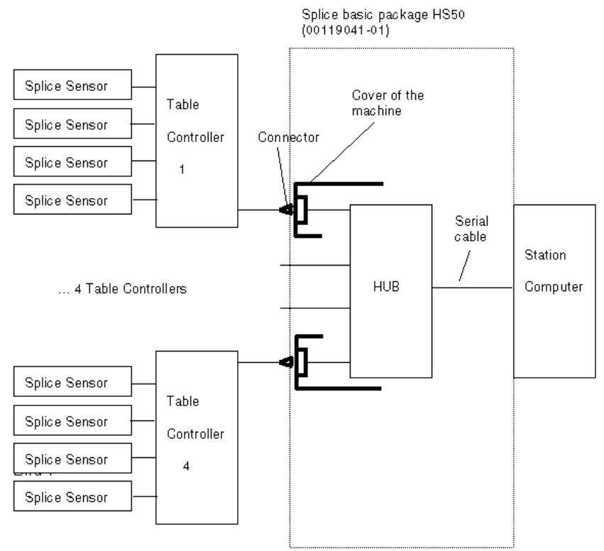
The basic splice detection package provides a link between the changeover tables, their commu-
nication units and splice sensors and the machine’s station computer. The basic package contains
all the components needed to prepare the HS50 for splice detection. 2
You will also have to upgrade each component changeover table with a retrofit kit. 2
2
Abb. 2.10 - 1 Structure of splice detection
Splice Detection Basis Package HS50:
00116936-01
"Splice Detection Station Package HS"
00119032-01
"Splice Detection Table
controller HS/D4"

2 Assembly instructions Splice Detection Basic Package SIPLACE HS-50 Splice Detection Basic Package HS-50
03/2008 Edition
18
2.2 Safety Instructions
2
DANGER
All the work described below must only be carried out by Siemens service engineers. 2
The safety instructions from the “Operational safety” chapter of the user manual or the ervice ma-
nual take precedence over these instructions. 2
SIPLACE placement machines are supplied main power voltage. Consequently parts of these sy-
stems carry dangerous voltages inside the machine frame, even when switched off at the main
switch. 2
Before starting any work switch the machine off at the main switch and disconnect it from the main
power supply. 2
Always follow the accident prevention regulations, DIN or other standards and special safety rules
applicable in your country. Always follow DIN EN 60204 and DIN VDE 105-100 when working in-
side the machine frame. 2
Pay attention to the information concerning residual voltages and electrostatic discharge (ESD) in
the Operating safety chapter. 2
During the retrofit, always secure the machine to prevent access by other people and to prevent
it being switched on again. 2
If the component cart is out of the machine or is not correctly coupled to the machine, do not con-
nect it electrically to the machine frame. 2
2
2.2.1 Definitions
DANGER
in terms of these instructions means that death, severe bodily injury or considerable material
damage WILL occur if the instructions about danger are not followed. 2
2
NOTE 2
2
2
Splice Detection Basic Package HS-50 2 Assembly instructions Splice Detection Basic Package SIPLACE HS-50
03/2008 Edition
19
2.3 Tools
– Metric hex ball end wrench set (also called “Allen” wrench)
– Diagonal cutters
– Cross point screwdriver (also called a “Phillips Head” screwdriver)
– A small flat bladed screwdriver
2.4 Parts
2.4.1 Contents HS50 Splice Detection Basic Package (item no.: 00116936-xx)
Number Description Item no.:
- 1 Retrofitting Instructions 00193363-01
- Various installation material
- 1 HUB Unit 00366091-02
- 1 COM Interface for SC 00368432-01
- 1 Adapter for COM Interface 00368552-01
- 1 Serial cable HUB - SR 00368431-01
- 1 Cable power supply HUB 00368322-01
- 2 Cables HUB – TC long 00368249-01
- 2 Cables HUB – TC short 00368250-01
- 2Covers left side 00368325-01
- 2 Covers right side 00368326-01
- 1 Retrofitting instructions table controller 00193364-01
- 1 Retrofitting Instr. Splice Sensor 2x8mm 00193365-01