00193363-03.pdf - 第22页
2 Assembly instructions Splice De tection Basic Package SIPLACE HS-50 Sp lice Detection Basic Package HS-50 03/2008 Edition 22 2.7 Inst alling the splice detection hardware 2.7.1 Hub module The hub is fitted beneath the …

Splice Detection Basic Package HS-50 2 Assembly instructions Splice Detection Basic Package SIPLACE HS-50
03/2008 Edition
21
: Insert the card into the slot and clamp in place.
: Close the computer case.
: Push the computer back into position and strap in place.
: Reconnect the power supply and all other connections.
2
You will have to enter the number of this COM port later when you install the traceability software. 2
2
The ports are numbered consecutively, starting from 1. If two COM ports were previously assi-
gned, your new port will be number 3. 2
2
2.6.1 Installation of drivers
Windows NT 2
With the COM card (Item no.: 00373380-01) an installation CD / floppy disks and an installation
manual are delivered. 2
: Install the driver as described in the manual.
Windows XP (from SW 505 on) 2
The necessary drivers are stored on the installation CD. When restarting the computer you will be
asked to insert the CD.
The computer will search for the drivers and install them. 2
2
2 Assembly instructions Splice Detection Basic Package SIPLACE HS-50 Splice Detection Basic Package HS-50
03/2008 Edition
22
2.7 Installing the splice detection hardware
2.7.1 Hub module
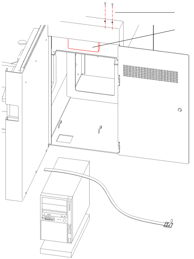
The hub is fitted beneath the side panel of the input conveyor (see Fig. 2.11 - 1). 2
2
Abb. 2.11 - 1 HUB module
2
: Loosen the screws for fixing the contact plug of the input flap (see Fig. 2.11 - 1).
2
2
Screws for
contact plug
HUB Unit
Splice Detection Basic Package HS-50 2 Assembly instructions Splice Detection Basic Package SIPLACE HS-50
03/2008 Edition
23
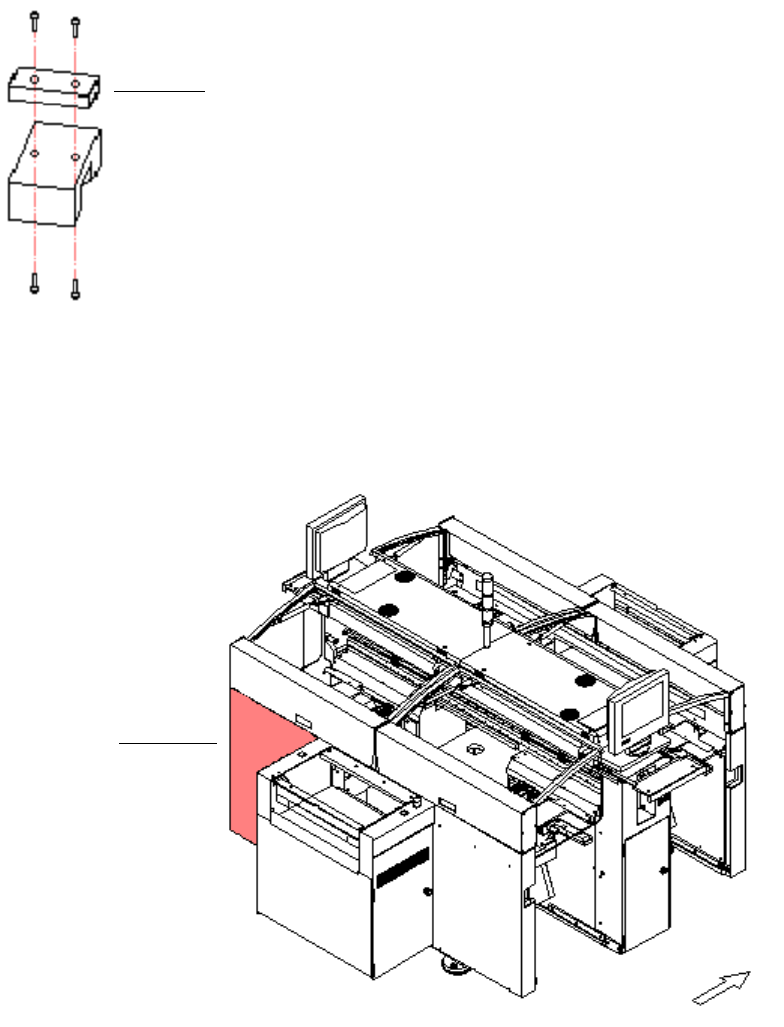
: Replace the distance piece with the mount for the hub, then reinstall the hub and contact plug.
2
Abb. 2.11 - 2 Distance piece
2
: Use the serial cable to connect the hub to the free COM port on the station computer.
2
Abb. 2.11 - 3 Distributor sector 4
2
: Detach the cover for the sector 4 distributor (see Fig. 16 - 3).
2
distance piece
sector 4