00198356-01_AI_Input-Extension_SX12_DE_EN_web.pdf - 第39页
39 Assembly Instructions / Montageanleitung SIPLACE SX1/SX2 V2 Option Input Conveyor Extension 05/2017 Table Of Contents Table Of Contents 1 Introduction .. 41 1.1 Safety Instructions .. 41 1.1.1 Conventions for the …
4 Anhang
4.1 Auszüge aus der Serviceanleitung
Assembly Instructions / Montageanleitung SIPLACE SX1/SX2 V2
Option Input Conveyor Extension 05/2017
38
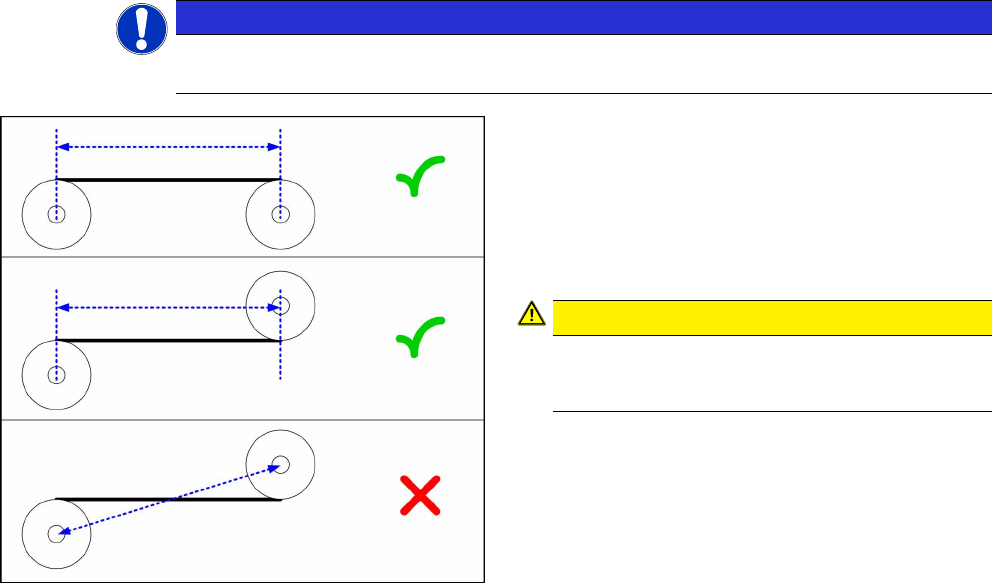
4.1.6.2 Berechnung der Riemenspannung
HINWEIS
Nur für Transportband
Diese Berechnung gilt ausschließlich für Riemen des Transportbandes.
Abb.23: Abstand messen
► Bestimmen Sie die beiden Umlenkrollen, zwi-
schen denen Sie die Riemenspannung einstellen
wollen. Wenn möglich vermeiden Sie es, dazu
die beweglichen Umlenkrollen zu verwenden.
► Messen Sie den Abstand zwischen den beiden
Umlenkrollen parallel zum Transportriemen.
(Siehe Bild)
VORSICHT!
Beachten Sie, dass an den Umlenkrollen
nicht immer einfach von Mitte zu Mitte ge-
messen werden kann.
.
► Berechnen Sie die Riemenspannung nach fol-
gender Formel:
(20000 / Umlenkrollenabstand [mm]) [Hz]
Die erlaubte Toleranz beträgt immer plus/minus 10%
des ermittelten Wertes.
Beispiel
Abstand zwischen den Umlenkrollen: 235mm
Berechnung:
20000 / 235 = 85 (gerundet, genau 85,106…)
10 % von 85,106… = 9 (gerundet, genau 8,5106…)
Ergebnis:
Riemenspannung: 85 +/-9 Hz
39
Assembly Instructions / Montageanleitung SIPLACE SX1/SX2 V2
Option Input Conveyor Extension 05/2017
Table Of Contents
Table Of Contents
1 Introduction.. 41
1.1 Safety Instructions.. 41
1.1.1 Conventions for the Use of Safety Instructions and Symbols.. 41
1.1.2 Safety Instructions for Working with Strong Magnetic Fields.. 42
1.1.3 Safety Instructions for the Power Supply (Without SMPS).. 42
1.1.4 Safety Instructions for the Power Supply (With SMPS).. 43
1.1.5 Safety Instructions for the Gantry.. 45
1.1.6 Safety Instructions on Hazardous Materials.. 45
1.1.7 Classification of the Optical Systems.. 46
1.1.7.1 Classification of the Whole Machine.. 46
1.1.7.2 Laser Classification.. 46
1.1.7.3 Classification of the Camera Systems.. 46
1.2 Preparatory Work..... 46
1.3 Other Instructions.. 48
1.3.1 Environmentally-Friendly Disposal of Materials and Components.. 48
1.3.2 Use of Original SIPLACE Accessories and Spare Parts.. 48
1.3.3 ESD Guidelines.. 48
1.3.3.1 Definition of ESD.. 48
1.3.3.2 Important Measures to Protect Against Static Charging.. 48
1.3.3.3 Handling ESD Modules.. 49
1.3.3.4 Measurements and Modifications to ESD Modules.. 49
1.3.3.5 Dispatching ESD Modules.. 49
1.3.4 Validity of Document.. 49
1.3.5 Release History.. 50
1.4 Staff Qualifications and Training.. 50
2 Brief description.. 51
2.1 Product description.. 51
2.2 Prerequisites.. 51
2.3 Scope of Delivery.. 52
2.4 Tools and equipment required.. 53
2.5 Required Working Time.. 53
3 Installation.. 55
3.1 Preparing the machine.. 56
3.2 Dismantling any available belt guides.. 57
3.3 Preparing the extensions.. 58
3.4 Installing the belt guide extension.. 59
3.5 Mounting the hand guard belt extension.. 60
3.6 Setting the belt tension.. 62
4 Appendix.. 63
4.1 Excerpts from the Service Manual.. 63
4.1.1 Replacing the Hexagonal Shaft [03094006-xx].. 63
4.1.2 Replacing the Tape Drive [03092315-xx].. 64
4.1.3 Replacing the conveyor drive [03092345-xx].. 65
4.1.4 Replacing the clamping rail and belt guide.. 66
40
Table Of Contents Assembly Instructions / Montageanleitung SIPLACE SX1/SX2 V2
Option Input Conveyor Extension 05/2017
4.1.5 Replacing the Toothed Belt (Conveyor Belt).. 68
4.1.6 Belt Tension.. 69
4.1.6.1 Setting the Tension of the Conveyor Toothed Belt.. 69
4.1.6.2 Calculating the Belt Tension.. 71