00198356-01_AI_Input-Extension_SX12_DE_EN_web.pdf - 第69页
Assembly Instructions / Montageanleitung SIPLACE SX1/SX2 V2 Option Input Conveyor Extension 05/2017 4 Appendix 4.1 Excerpts from the Service Manual 69 ► Loosen the top two idler pulleys (1) . ► Loosen the screws fasteni…
4 Appendix
4.1 Excerpts from the Service Manual
Assembly Instructions / Montageanleitung SIPLACE SX1/SX2 V2
Option Input Conveyor Extension 05/2017
68
Installation
► Follow the removal instructions in reverse order for installation. Also observe the following in-
structions:
CAUTION
Installation Instructions
► Tighten the screws fastening the clamping rail / belt guide with a torque of 6Nm. Oth-
erwise, the thread could be damaged or the conveyor rail could be distorted.
► Check the setting for the transmitter / receiver and correct it if necessary (see Setting
and Correcting the Laser Light Barrier).
► Once you have loosened the conveyor belt, set the tension again (see 4.1.6.1 "Setting
the Tension of the Conveyor Toothed Belt" [}69]).
4.1.5 Replacing the Toothed Belt (Conveyor Belt)
Parts, equipment and tools
●
Toothed belt
Select the relevant toothed belt:
Input area Placement area Output area
Toothed belt Synchronous belt
L=1239mm
[03093312‑xx]
Synchronous belt
L=1500mm
[03093146‑xx]
Synchronous belt
L=1158mm
[03093314‑xx]
●
Bearing for hexagonal shaft SXa (plastic bearing) – pack of 10 [03092024-xx]
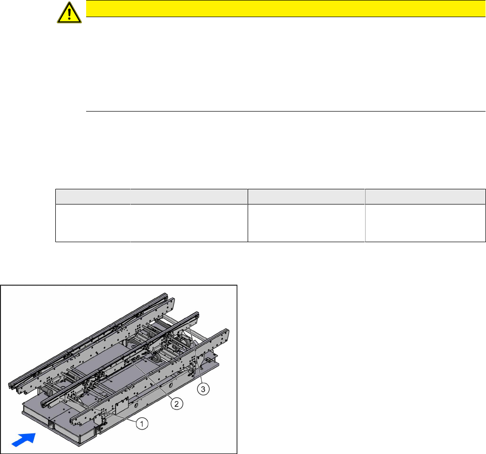
Overview
1. Toothed belt input area
2. Toothed belt placement area
3. Toothed belt output area
Removal
► Use the software to move the conveyor rails into a position which allows you best access. Al-
ternatively, you can also loosen the conveyor rail clamps on the dual conveyor.
► Switch off the machine, disconnect it from the power supply and secure it to prevent unauthor-
ized reactivation. Observe the instructions in section 1.2 "Preparatory Work..." [}46].
► Loosen the hexagonal shaft on the belt drive or conveyor drive (motor), so that you can move
the shaft freely. To do this, dismantle the hexagonal shaft fixture on one side and the corres-
ponding plastic bearing on both sides (see also 4.1.1 "Replacing the Hexagonal Shaft
[03094006-xx]" [}63]).
► Loosen the movable idler pulley (see also 4.1.6.1 "Setting the Tension of the Conveyor
Toothed Belt" [}69]).
Assembly Instructions / Montageanleitung SIPLACE SX1/SX2 V2
Option Input Conveyor Extension 05/2017
4 Appendix
4.1 Excerpts from the Service Manual
69
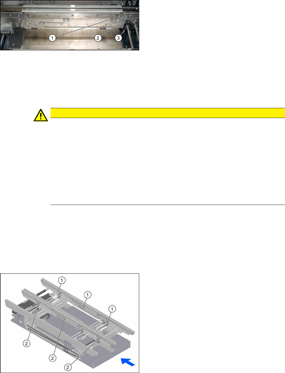
► Loosen the top two idler pulleys(1).
► Loosen the screws fastening the belt drive (3)
and the conveyor drive.
► If you replace a conveyor belt in the placement
area, you will also need to loosen the top retain-
ing screw (2) on the spring. Make sure that you
do not lose the spring and the bushing on the
screw. When you refit them, check the bushing
for correct orientation.
► Carefully unthread the conveyor belt.
Installation
► Follow the removal instructions in reverse order for installation. Also observe the following in-
structions:
CAUTION
Installation instructions
► Check the new toothed belt before fitting it. Hold it up high. It should hang loose and
should not twist.
► Make sure that the toothed belt is not folded or damaged otherwise.
► Make sure that the toothed belt is positioned accurately in the guidance on the motor
shaft or in the belt drive.
► If you have loosened the spring, check the bushing for correct orientation when you fit
it back again (see also Replacing the Tension Spring on the Clamping Plate
[03088949-xx]).
► While tightening the movable idler pulley, set the tension of the toothed belt correctly
(see 4.1.6.1 "Setting the Tension of the Conveyor Toothed Belt" [}69]).
4.1.6 Belt Tension
The precalculated values for setting the belt tension can be found in the following chapters.
In addition, the value for any section of the conveyor belt can be calculated using a formula. (See
4.1.6.2 "Calculating the Belt Tension" [}71])
4.1.6.1 Setting the Tension of the Conveyor Toothed Belt
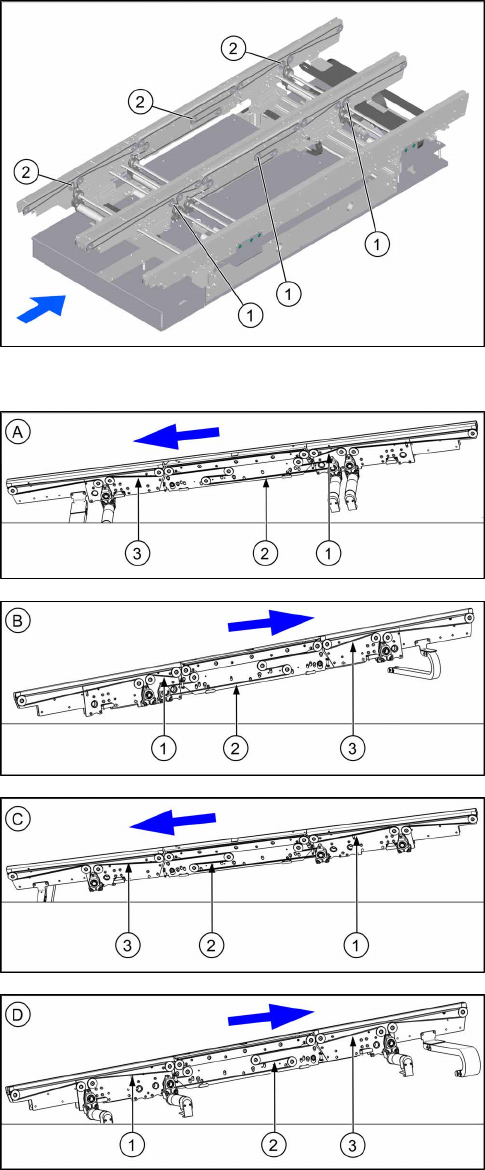
Overview of Movable Idler Pulleys
1. Movable idler pulleys on conveyor rail A
2. Movable idler pulleys on conveyor rail C
4 Appendix
4.1 Excerpts from the Service Manual
Assembly Instructions / Montageanleitung SIPLACE SX1/SX2 V2
Option Input Conveyor Extension 05/2017
70
1. Movable idler pulleys on conveyor rail B
2. Movable idler pulleys on conveyor rail D
Overview of Measuring Points and Values
Right conveyor lane 1 – conveyor rail A
1. Input area: 250 +/- 15 Hz
2. Placement area: 50 +/- 5 Hz
3. Output area: 125 +/- 13 Hz
Left conveyor lane 1 – conveyor rail B
1. Input area: 250 +/- 15 Hz
2. Placement area: 50 +/- 5 Hz
3. Output area: 125 +/- 13 Hz
Right conveyor lane 2 – conveyor rail C
1. Input area: 80 +/- 8 Hz
2. Placement area: 175 +/- 18 Hz
3. Output area: 100 +/- 10 Hz
Left conveyor lane 2 – conveyor rail D
1. Input area: 80 +/- 8 Hz
2. Placement area: 175 +/- 18 Hz
3. Output area: 100 +/- 10 Hz
Setting
► Use the software to move the conveyor rails into a position which allows you best access. Al-
ternatively, you can also loosen the conveyor rail clamps on the dual conveyor.
► Switch off the machine, disconnect it from the power supply and secure it to prevent unauthor-
ized reactivation. Observe the instructions in section 1.2 "Preparatory Work..." [}46].
► Check the tension at the relevant measuring point.
► If the tension is not correct, loosen the screw fastening the movable idler pulley and correct
the tension.