00198356-01_AI_Input-Extension_SX12_DE_EN_web.pdf - 第55页
Assembly Instructions / Montageanleitung SIPLACE SX1/SX2 V2 Option Input Conveyor Extension 05/2017 3 Installation 2.5 Required Working Time 55 3 Installation CAUTION Do not loosen the wrong screws The following applies …
2 Brief description
2.5 Required Working Time
Assembly Instructions / Montageanleitung SIPLACE SX1/SX2 V2
Option Input Conveyor Extension 05/2017
54

Assembly Instructions / Montageanleitung SIPLACE SX1/SX2 V2
Option Input Conveyor Extension 05/2017
3 Installation
2.5 Required Working Time
55
3 Installation
CAUTION
Do not loosen the wrong screws
The following applies to all work performed on the conveyor:
► Make sure you do not loosen any screws other than those explicitly specified. Loosen-
ing other screws could lead to irreparable misalignment or damage to the conveyor.
3 Installation
3.1 Preparing the machine
Assembly Instructions / Montageanleitung SIPLACE SX1/SX2 V2
Option Input Conveyor Extension 05/2017
56
3.1 Preparing the machine
► Use the software or manually move the conveyor rail into a position which allows you best ac-
cess.
CAUTION
Moving the conveyor rails
The conveyor rails are highly sensitive and should therefore not be moved unless you have
released the brakes.
If you do move them without releasing the brakes, this could cause irreparable dam-
age to the conveyor rails.
► We recommend that you use the software to help you move the conveyor rails.
► If this is not possible, the conveyor rails of the dual conveyors can also be moved by
manually docking in the adjustment units. Make sure that the cylinders engage in all
clamping units of a particular conveyor rail. The conveyor rails can then be moved by
carefully pulling the toothed belt of the width adjustment unit.
► If this is not possible either, the brakes of the dual conveyors can manually be re-
leased using a pin. Take special care not to distort the conveyor rails.
► Switch off the machine, disconnect it from the power supply and secure it to prevent
unauthorized reactivation. Observe the instructions in section 1.2 "Preparatory Work..." [}46].
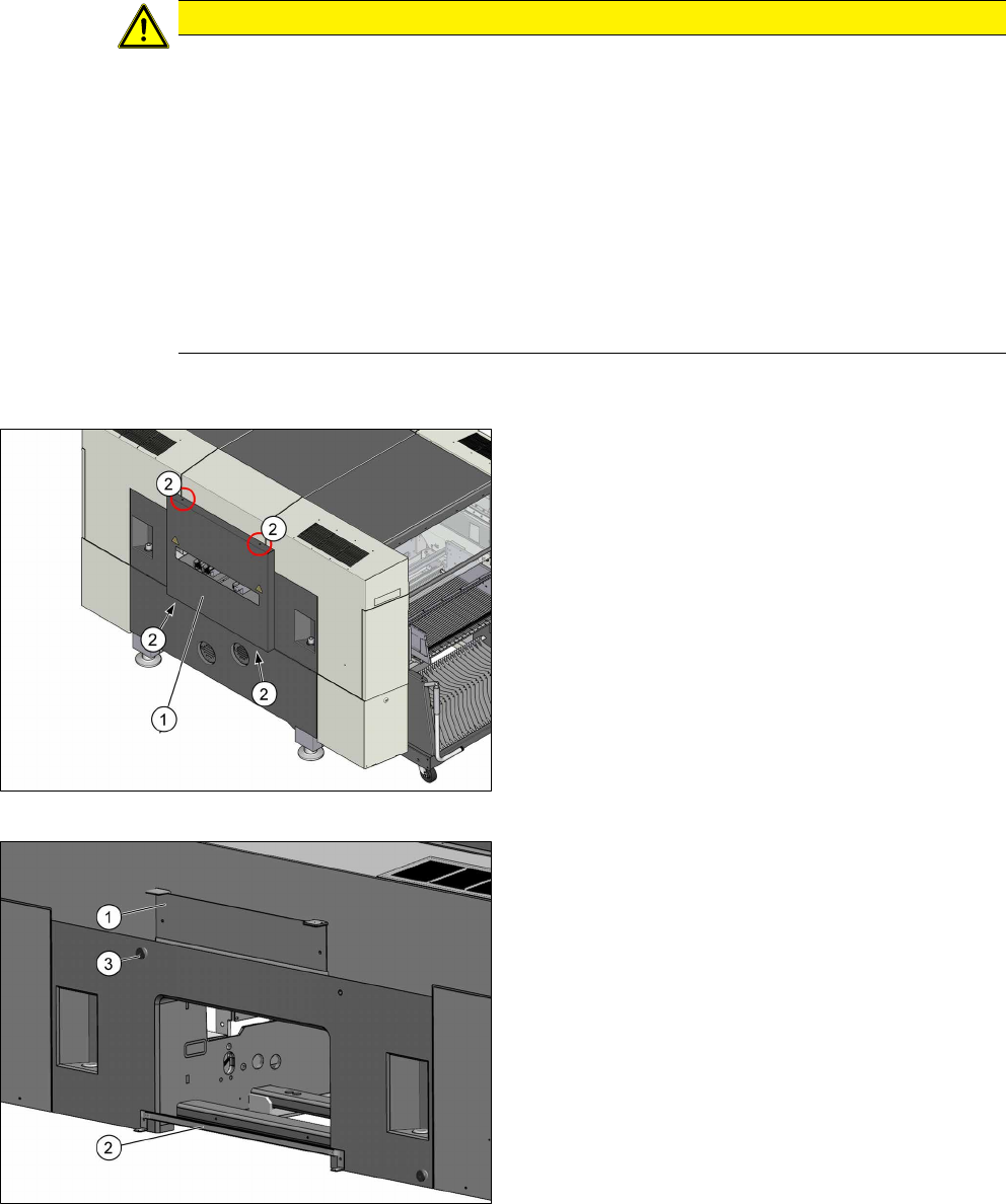
Fig.6: Cover on the input side
► Remove the four screws (2) fastening the cover
(1) (tiny backpack) and remove the cover.
Fig.7: Brackets
► Remove the top bracket (1).
► Remove the bottom bracket (2) (guide rail for
PCB barcode).
► Remove the stop roll (3).