HS50 circuit diagram.pdf - 第82页
2 Circuit Diagr ams 82 I 0033589 1-010 201LD3 S ervo uni t withou t boar ds (Sh. 1 of 2) = SIEMENS A G + X-P3 +6/100 Volt s Anti-crash P2/P3 X52/1 2 Y-P2 Y-P1 X51/b 30 X50 /b30 Anti-cr ash P1 /P 4 X52/1 0 X4vw/2 X4vs/2 D…
2 Circuit Diagrams 81
I
00334810-020103TD3 HS-50 servo unit, viewed from the front (Sh. 2 of 2)
Function status
Product status
Doc. status
SMD Placement System SIPLACE HS50
damages. All rights are reserved in the event of the grant of
out express authority. Offenders are liable to the payment of
or communication of the contents thereof, are forbidden with-
Copying of this document, and giving it to others and the use
Schadenersatz. Alle Rechte fuer den Fall der Patenterteilung
ausdruecklich zugestanden. Zuwiderhandlungen verpflichten zu
Weitergabe sowie Vervielfaeltigung dieser Unterlage, Verwer-
tung und Mitteilung ihres Inhalts nicht gestattet, soweit nicht
oder GM-Eintragung vorbehalten.
a patent or the registration of a utility model or design.
26.01.99
Status Modified Date Name
Scale
Date
Name
Author
Check.
Stand.
(Drawing number)
Main no.
Sheet
Sh.
’U-nom (U)’
’0V’
’U-nom (W)’
’I-act (W)’
’I-act (U)’
’I-nom (W)’
’I-nom (U)’
Output of curr. ctrl
Current, act. val.
Current, act. val.
Current, nom. val.
Ready for operation
Release power stage
r.m.s. current limit. (I²xt signal)
Error
MP1
MP2
MP3
MP4
MP5
MP6
MP7
MP8
Current, nom. val.
n.u.
Ref. potential
Output of curr. ctrl
(viewed from the front)
00334810-020103TD3
2
HS50 servo unit
A3
2
02.
10.09.1997 Goller
30.09.98
30.09.98
26.01.99
Tek
Tek
Tek
01.
03.
Motor ctrl. output(output current ctrl.)
Current,nom. val.(output rot. speed ctrl.)
Tacho (real tacho voltage)
GND of amplifier electronics
Sensor-stop signal
Actual value of current
Nom. value, power input
Nom. value of rotational speed
0V
Ss
Ii
IA
Is
Ta
Ie
Ns
Offset
r.m.s. current
Peak current
P gain
Error
r.m.s. current limit. (I²xt signal)
Release power stage
Tachometer
Ready for operation
Power supply +/-15VAnticrash board
Servo board TBS120 Servo board TDS120
Servo board X axis
TBS200/10X
Servo board star
TBS120/2.5S
Servo board Y axis
TBS200/15Y
Servo board Z axis
TDS120A2.5Z TDS120/1D
Servo board dp axis
Reset
Distance
FS ES US UA S F
See page 151
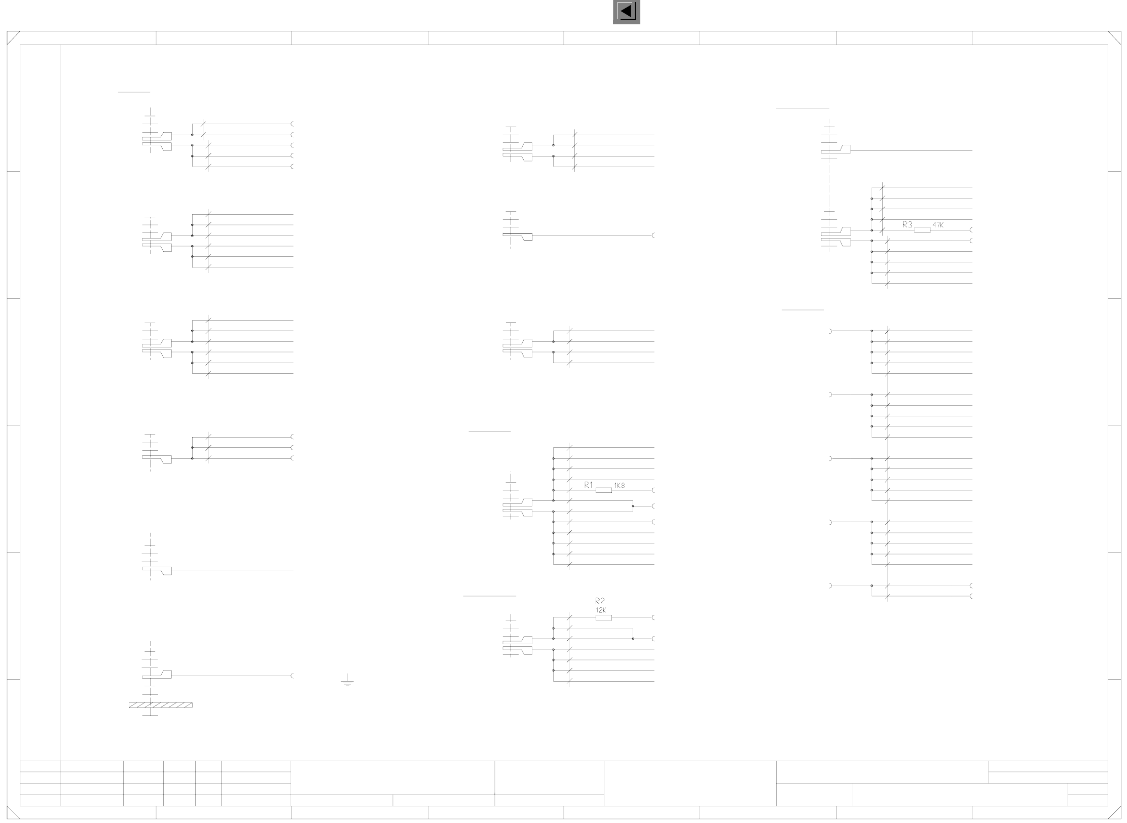
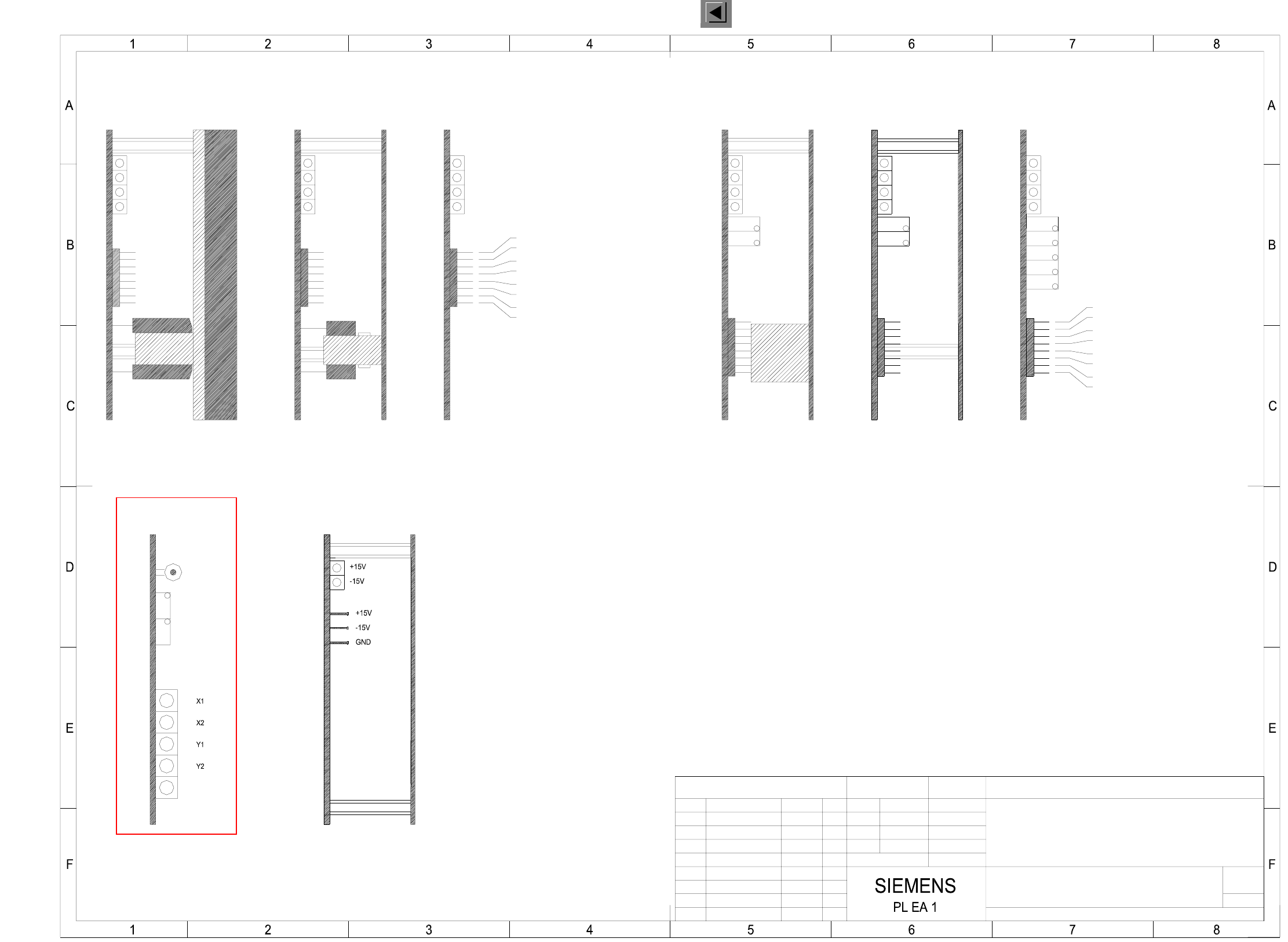
2 Circuit Diagrams 82
I
00335891-010201LD3 Servo unit without boards (Sh. 1 of 2)
=
SIEMENS AG
+
X-P3
+6/100 Volts
Anti-crash P2/P3
X52/12
Y-P2
Y-P1
X51/b30
X50/b30 Anti-crash P1/P4
X52/10
X4vw/2
X4vs/2
DP
Z
S
Y
X4vo/2
X6vh/2
X6vd/2
bk (UL) / 2.5mm²
Contact washer
Z
S
Y
X4vn/2
X6vg/2
Y
Lateral part
X4vr/3
Z-P1
X4vq/2
DP
Z
S
Y
X4vm/2
X6vf/2
X6vb/2 X-P4
X52/4
X4vt/2
X4vp/2
DP
Z
S
gnye (UL) / 2.5mm²
Plain washer
Retainer ring
M5 nut
X52/6
X4vu/2
X4vv/2
X52/8
FF
E
D
C
B
A
Weitergabe sowie Vervielfaeltigung dieser Unterlage, Ver-
wertung und Mitteilung ihres Inhalts nicht gestattet, soweit
nicht ausdruecklich zugestanden. Alle Rechte vorbehalten, ins-
besondere fuer den Fall der Patenterteilung oder GM-Eintragung. Bauteilangaben nur zur Information
Comunicado como segredo empresarial. Reservados todos os direitos.
Confie a titre de secret d’entreprise. Tous droits reserves.
Proprietary data , company confidential . All rights reserved.
Confiado como secrete industrial. Nos reservamos todos los derechos.
SMD-Placement System Siplace HS50
Product status
Doc. status
Function status
Status DateModified Name Stand. Orig. Replacement for Replaced by
Author
Date
Check.
Sheet
Sh.
X4vp/4
0 Volts
Plain washer
Plain washer
Plain washer
Plain washer
X9ym
Ballast
Plain washer
Retainer ring
Screw, M5X12
X7vf/2
M6 nut
+30 Volts
X1ym
Plain washer
Retainer ring
Screw, M5X12
wh (UL) / 1.0mm²
wh (UL) / 2.5mm²
X4vr/2
DP
245678
12345678
A
Screw, M5X12
X4vs/4
X4vw/4
X4vv/4
X4vo/4
X4vn/4
X4vr/4
X4vq/4
X4vu/4
X4vt/4
X4vm/4
M5 nut
B
C
D
E
X7vh/2
X7vd/2
X7vg/2
Screw, M5X12
X7vc/2
X10ym
X-P3
Y-P2
Y-P3
Plain washer
Retainer ring
wh (UL) / 2.5mm²
X-P2
wh (UL) / 2.5mm²
Plain washer
Retainer ring
Mutter M8
X6ym
N30
Plain washer
Retainer ring
Screw, M5X12
HEP
1
M6 nut
S-P2
X4vw/3
X4vu/3
DP-P3
DP-P2
Z-P3
Plain washer
X7vb/2
X7ve/2
Screw, M5X12
X7va/2
X8ym
X-P4
Y-P1
Y-P4
Plain washer
Retainer ring
wh (UL) / 2.5mm²
X-P1
X4vo/3
X60/1
X4vk/3
X3yn
gr (UL) / 0.75mm²
Retainer ring
M5 nut
wh / 0.34mm²
Anti-crash P1/P4
Retainer ring
Screw, M5X12
X4vk/4 S-P1
X4ym
Resistors R1-R3 (and their soldered joints) are insulated using heat-shrinkable sleeves !
DP-P1
Z-P4
Plain washer
Retainer ring
wh (UL) / 1.0mm²
Z-P1
X3ym
Power supply unit
TP 0V
Anti-crash P2/P3
wh (UL) / 1.5mm²
Power supply unit
Plain washer
From external power supply
X7ym
N200
X53/16
X7va/1
X-P3
Ballast
X-P2
X4vv/3
X52/32
DP-P1
Power supply unit
X2yn
X60/2
X4vq/3
X4vp/3
X4vt/3
3
Z-P4
P30
Z-P3
TP 30V
X-P1
Plain washer
Retainer ring
M6 nut
S-P4
S-P3
S-P2
DP-P4
DP-P3
DP-P2
X4vm/3
X4vn/3
X4vk/2
X6ve/2
X6va/2 X-P1
or / 0.34mm²
TP 6/100V
X2ym
S-P1
P6/100
Plain washer
Retainer ring
Z-P2
Y-P4
Y-P3
Z-P2
From external power supply
+15 Volts
+200 Volts
S-P4
DP-P4
X7vf/1
X7vh/1
X7vg/1
X7ve/1
X7vb/1
X7vd/1
X7vc/1
X-P4
bk (UL) / 1.5mm²
X4yn TP 200V
bk (UL) / 0.75mm²
X11ym
Plain washer
Retainer ring
M6 nut
X4vs/3
X6vc/2 X-P2
X5ym
S-P3
X60/4
1
Servo unit, without boards
#
Goller
21.01.1998
09.12.98
09.12.98
21.01.98
1.
2.
1.
Tek
Tek
Tek
2
00335891-010201LD3
X1yn
X53/22
X60/3
X52/16
X51/b31
X60/12
PL EA1 E2
X50/b31
X52/30
X60/11
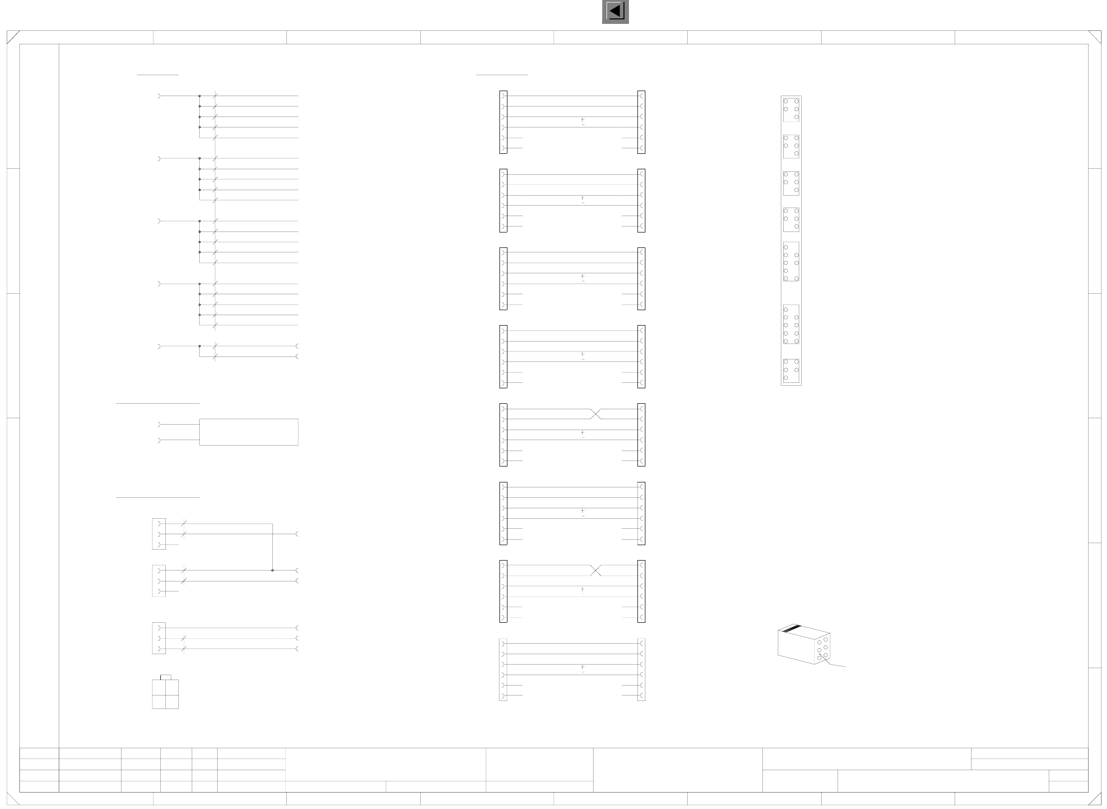
2 Circuit Diagrams 83
I
00335891-010201LD3 Servo unit without boards (Sh. 2 of 2)
Weitergabe sowie Vervielfaeltigung dieser Unterlage, Ver-
wertung und Mitteilung ihres Inhalts nicht gestattet, soweit
nicht ausdruecklich zugestanden. Alle Rechte vorbehalten, ins-
besondere fuer den Fall der Patenterteilung oder GM-Eintragung. Bauteilangaben nur zur Information
Comunicado como segredo empresarial. Reservados todos os direitos.
Confie a titre de secret d’entreprise. Tous droits reserves.
Proprietary data , company confidential . All rights reserved.
Confiado como secrete industrial. Nos reservamos todos los derechos.
SMD-Placement System Siplace HS50
Product status
Doc. status
Function status
Status DateModified Name Stand. Orig. Replacement for Replaced by
Author
Date
Check.
Sheet
Sh.
Tacho-X4
Enable
Tacho-Y4
Enable
Tacho-X2
Enable
Tacho-Y2
Enable
Tacho-X3
Enable
Tacho-Y3
S
Z
DP
X4vp/1
Key Key
b28 = Distance sensor, analog
Ventilation OK
X60/9
P24
a26 = Distance sensor, digital
Key Key
Key
Key Key
Key
Key Key
b21 = Distance sensor analog
b27 = B2-prox. switch Y4 [Y3]
a19 = Distance sensor, digital
1324567
Y
S
Z
DP
4 78
5
9
13
D
E
FF
Key
Key
Enable
Key
Key
Y
S
Z
DP
X4vs/1
X4vw/1
X52/24
bl / 0.34mm²
X-P1
X6va/1
X6ve/1
X4vk/1
Y
Y1 [Y2] - gantry
X4 [X3] - gantry
Y4 [Y3] - gantry
b
X51b7
X51a13
X51b13
b31 = 0 Volts
a31 = Crash signal
b32 = -15V
17
24
b17 = Ref. prox. switch X1 [X2]
b18 = B2-prox. switch X1 [X2]
Null
Key
Key
0.34mm²
X6vb/1
X6vf/1
X4vm/1
Y
S
Z
DP
X4vq/1
X4vu/1
X52/20
X-P2X6vc/1
X6vg/1
X4vn/1
X1ua/2
X1ua/1
X
X
X4vr/1
X4vv/1
X5va/3
C
B
A
X50a10
X50a9
X50b9
XX
X
XX
X
X50 [X51]
X1 [X2] - gantry
Gantry 1 [2]
Gantry 4 [3]
(Prox. switches)
(Prox. switches)
X=pinched off
1
30
X5vb/6
X5vc/2
X5vc/1
X5vc/4
a
a30 = Control On
b30 = +15V
X
X
X
65
b20 = B2-prox. switch Y1 [Y2]
b24 = Ref. prox. switch X4 [X3]
b25 = B2-prox. switch X4 [X3]
b26 = Ref. prox. switch Y4 [Y3]
X5vg/3
X5vg/6
X5vh/2
X5vh/1
X5vh/4
X5vh/3
X5vh/6
pk
vi
X60/6 Control On
bn
X1ua
bn
Crash signal P2/P3
X50a3
X50b3
X5va/2
X5va/1
X
E
D
X51a15
X51b15
X5vf/2
X5vf/6
X5vg/2
X5vg/1
X5vg/4
X51b1
X51a2
X51b2
X51a3
X51b3
X51a9
X51b9
X51a10
X51b10
X51a11
X51b11
X5vb/2
X5vb/1
X5vb/4
X5vb/3
X50/a32
X51/a30
X51/a31
X51/a32
X5vc/3
X
X
X5vd/1
X5vd/4
X5vd/3
X
X
X
X50a6
X50b6
X50a7
X50b7
0.34mm²
gn / 0.34mm²
0.5mm²
rd (UL)
bk (UL)
12
34
Viewed from
cable entry side
X50a1
X50b1
X50a2
X50b2
X50a5
X50b5
X52/22
X-P3
X5va/4
X51a14
X51b14
X6vd/1
X6vh/1
X4vo/1
X5vf/1
X5vf/4
X5vf/3
X50b10
X50a11
X50b11
X51a1
bl / 0.34mm²
Anticrash P1/P4X50/b32
X51/b32
X52/26
Anticrash P2/P3
-15 Volts
Ballast resistor
External
Ballast resistor
X53/10
X53/30
Anti-crash/fan
X50/a30
X50/a31
Tacho-X1
Anticrash
X60/8
X60/7
X60/5 Crash signal P1/P4
X60/10
X
X51a7
XX
X5ve/2
X5ve/1
X5ve/4
X5ve/3
X5ve/6
b19 = Ref. prox. switch Y1 [Y2]
X50a13
X50b13
X50a14
X50b14
X50a15
X50b15
X51a5
X51b5
X51a6
X51b6
X
X1ua/4
X5vc/6
X5vd/2
X5vd/6
2
Tek
Tek
Tek
1.
2.
1.
21.01.98
09.12.98
09.12.98
21.01.1998
Goller
#
Servo unit without boards
2
X
X4vt/1
X52/18
X-P4
X5va/6
00335891-010201LD3
PL EA1 E2
the numerical sequence of a Locking-clip connector
Make sure that ...
must be as viewed from the rear side of the casing.
Cable
=
SIEMENS AG
+
3
5
2
4
6
1
Enable
a21 = 0 Volts analog
Key Key
a28 = 0 Volts analog
8
123
Tacho-Y1
Enable
A
B
C