HS50 circuit diagram.pdf - 第91页
2 Circuit Diagr ams 93 I 0033615 3-030 104LD3 Di stributo r , sector 4 (Sh. 1 o f 4) Function sta t. Product stat. Document stat. Status Modified Date Name Stand. Check. Author Date Orig. Repl. f. Replaced by Distribut o…
2 Circuit Diagrams 90
I
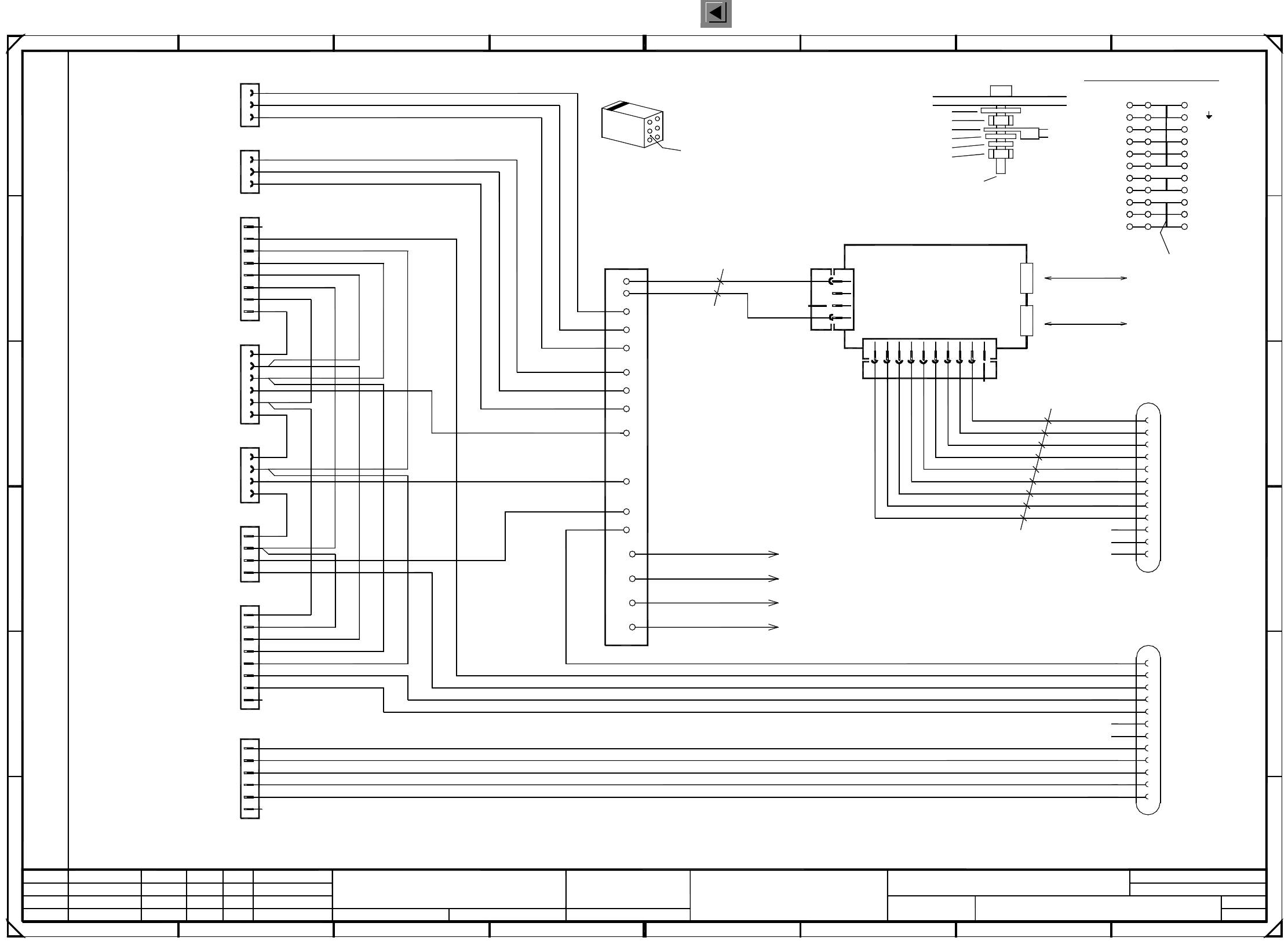
00336152-030103LD3 Distributor, sector 1 (Sh. 1 of 2)
=
SIEMENS AG
+
GND
+5V
+24V
Voltages ring circuit
Sec4<>Sec1
Voltages ring circuit
Sec1<>Sec2
Infeed
Socket 1, peripheral modules
StartStopInputRight
Emerg.StopPCBInput
Safety ring circuit
Sec4<>Sec1
Safety ring circuit
Sec1<>Sec2
5
B
SMD Placement System SIPLACE HS50
4
X1af
A7
A10
+24V
+24V
1P34V
P8V
N8V/34V
GND
+5V
+24V
876
D
2
X3ag and X4ag ,
X100 terminals overview
X5af
X2af
X8af
X4af
X6af
X3af
Hood1
All control lines: 1.00mm² / black
Cable ties are used to form the cable harness !
+24V
X25af
CompFlap1
X7af
2
F
A module
M5 split washer, DIN 7980
M5x16 fillister head screw, DIN 912
3
5
2
4
6
1
M5 hexagon nut, DIN 439
Distributor sheet
Locking clip plug:
To Harting plug housing (from X1)
PE
A11
N8V/34V
6
1
P8V
32
C
+5V
CAN_INT
CAN_RESET
GND
+5V
GND
A
Ground connection :
Contact washer
M5 hexagon nut, DIN 439
Annular cable lug
B5
B6
B9
B8
B7
10
B module
CANL
CANH
3
4
5
76
X3ag
X4ag
B10
B11
B12
B2
34
A6
+5V
C
A3
A8
A4
E
gnye
00336788gnye
00336789gnye
00336790
PE
PE
8
B
5
1
D
1
A9
A1
A2
X3ag
X2ag
M5 washer, DIN 125
X1ag
500kbps
CAN bus
500kbps
X5ar - X16ar
B4
key
key
B1
A5
A
8
A12
2
3
CAN bus
1P34V
To cover
To distributor sheet
To machine frame
0.56mm² / bk
Bridge
A1 CAN-bus coupler
00332557 (ag)
0.56mm² / bk
00336787
X100
7
ab c
GND
F
03.
01.
03.
Tek
Tek
Tek
2
gnye
B3
+24V
X1af
GND
X4ag
E
4b
1a
2c
4c
109
24.03.99
1
00336152-030103LD3
Distributor, sector 1
Hoffmann
11.12.1997
10.04.00
24.03.99
Document stat.
Product stat.
Function stat.
3
5
4
1
2
3
6
6
7
4
5
3
1
2
8 / 9
4
2
1
2
3
4
PE
PE
5
4
6
7
1
3
PL EA1 E2
5
1
1
3
6
2
4
1
3
2
2
8 / 9
1
2
3
1
2
3
4
5
8
8
29
must be as viewed from the rear side of the casing.
Cable
GROUND
7
PE
6a
7a
7b
7c
3c
that the numerical sequence of a locking clip plug
Please note that ...
4a
PE
16
71
1
5
4
4
3
3
2
6
6c
2a
4
Spare
Spare
Spare
Address bit 1
GND_Address
Address bit 0
S_Begin
L_Begin
L_End
S_End
Spare
Spare
PCC11
PCC12
ModifiedStatus Stand.Date Name
Orig. Replaced byRepl. f.
Author
Check.
Date
Spare
S_CompEnd
S_hood
S_StartButton
S_Emerg.StopButton
S_CompFlap
S_StopButton
L_End
L_Begin
S_Emerg.StopButton
S_StartButton
S_StopButton
L_End
L_Begin
S_hood
L_End
L_Begin
S_CompFlap
L_End
S_StopButton
S_CompFlap
S_Emerg.StopButton
S_StartButton
S_hood
L_End
S_CompEnd
Spare
PCC11
PCC12
Spare
Sheet
Sh.
2 Circuit Diagrams 93
I
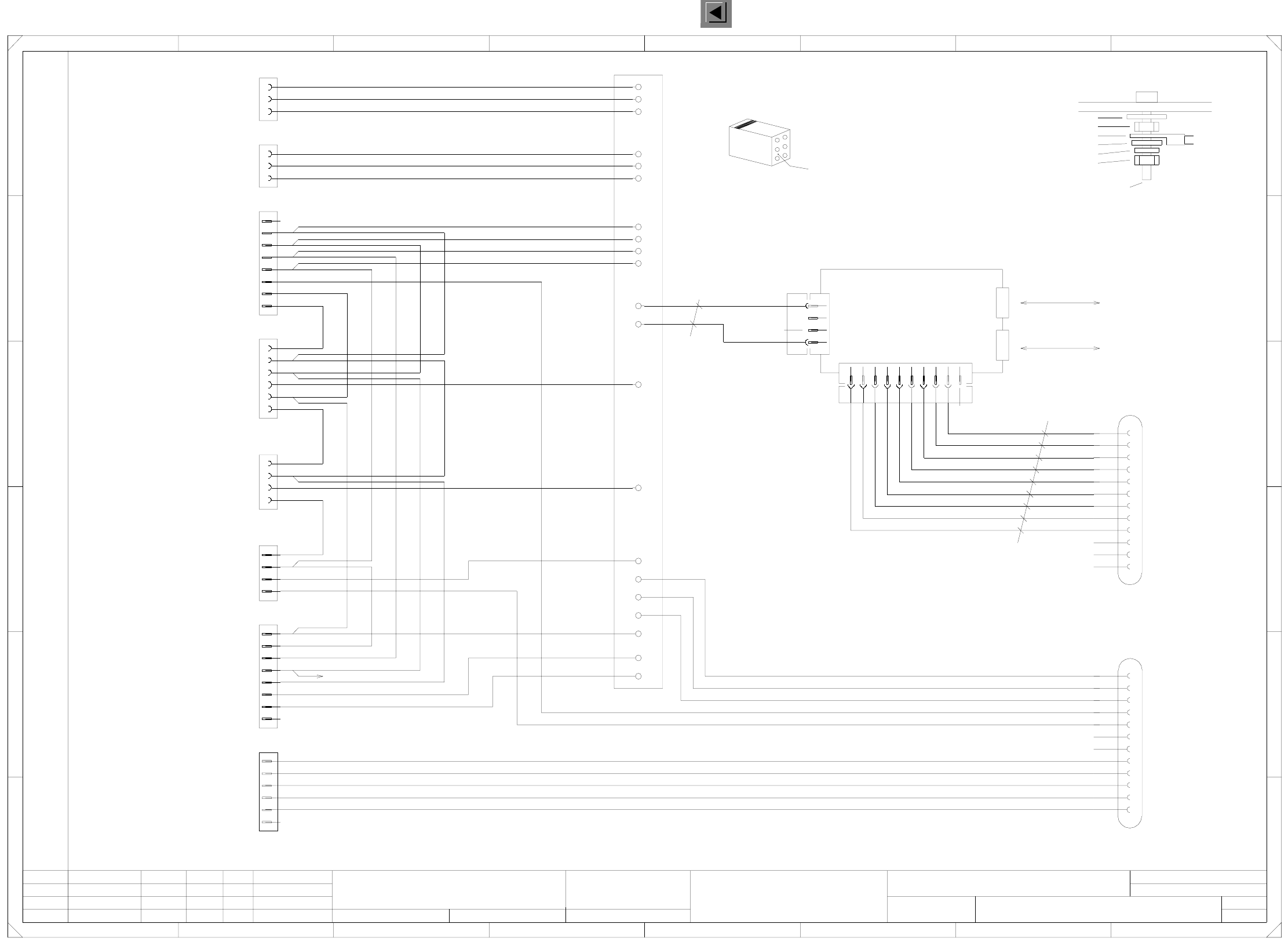
00336153-030104LD3 Distributor, sector 4 (Sh. 1 of 4)
Function stat.
Product stat.
Document stat.
Status Modified Date Name Stand.
Check.
Author
Date
Orig. Repl. f. Replaced by
Distributor, sector 4
SMD Placement System SIPLACE HS50
Sheet
Sh.
Voltages ring circuit
Sec3<>Sec4
Voltages ring circuit
Sec4<>Sec1
HoodPCBInput
LeftStartButtonOn
Safety ring circuit
Sec3<>Sec4
CompFlap4
Hood4
Spare
S_StopButton
S_CompEnd
S_hood
S_StartButton
S_Emerg.StopButton
S_CompFlap
L_End
L_Begin
S_hood
S_StartButton
L_End
S_StopButton
L_Begin
S_hood
L_End
L_Begin
S_CompFlap
L_End
Socket 4, peripheral modules
Infeed
Sec4<>Sec1
Safety ring circuit
S_CompFlap
S_CompEnd
S_hood
S_StartButton
S_Emerg.StopButton
L_End
Spare
S_StopButton
PCC41
PCC42
Spare
Cable
Locking clip plug: X3dg and X4dg ,
M5 washer, DIN 125
Annular cable lug
M5 hexagon nut, DIN439
M5 split washer, DIN 7980
M5 hexagon nut, DIN439
Contact washer
Ground connection :
Distributor sheet
M5x16 fillister head screw, DIN 912
must be as viewed from the rear side of the casing.
that the numerical sequence of a locking clip plug
Please note that ...
A1 CAN-bus coupler
bk
CAN bus
CAN bus
bk
Address bit 0
GND_Address
Address bit 1
Spare
Spare
Spare
B module
A module
L_End
S_End
S_Begin
L_Begin
Spare
Spare
Cable ties are used to form the cable harness !
All control lines: 1.00qmm / black
Bauteilangaben nur zur Information
Weitergabe sowie Vervielfaeltigung dieser Unterlage, Ver-
wertung und Mitteilung ihres Inhalts nicht gestattet, soweit
nicht ausdruecklich zugestanden. Alle Rechte vorbehalten, ins-
besondere fuer den Fall der Patenterteilung oder GM-Eintragung.
Comunicado como segredo empresarial. Reservados todos os direitos.
Confie a titre de secret d’entreprise. Tous droits reserves.
Proprietary data , company confidential . All rights reserved.
Confiado como secrete industrial. Nos reservamos todos los derechos.
0.56mm²
3
5
2
4
6
1
=
SIEMENS AG
+
X2df
X1df
A7
A10
A11
A12
A5
A3
+24V
+24V
GND
SSK41
SSK42
1P34V
GND
+5V
+24V
GND
+5V
X7df
X6df
X25df
X5df
X4df
X3df
X8df
+24V
A8
A4
A6
A9
A1
A2
X4dg
Modul B
X1df
E
P8V
N8V/34V
8
(dg)
4
B4
B5
B6
B9
B7
GND
1P34V
P8V
N8V/34V
X3dg
1 4
+24V
X400
X10df_2
E
F
00332557
A
B
56
key
10
X1dm - X16dm,
X1dn - X16dn
+5V
X3dg
0,56qmm
832
F
67
X1dg X2dg
500kbps
1
B8
CANL
CANH
CAN_INT
CAN_RESET
A
B1
500kbps
key
2
3
D
7
B
5
B10
B11
B12
X4dg
GND
+5V
C
23
B2
B3
C
D
9c
4
Tek
Tek
Tek
03.
01.
04.
25.03.99
27.01.00
11.12.1997
Hoffmann
00336153-030104LD3
1
25.03.99
2
3
4
1
8
3
13a
20b
11c
9b
6
3
2
1
9a
7b
1c
9
910
1
7
6
3
6
7
7
8
4
5
4
1
1
2
3
4
1
3
2
4
5
24a
1
2
8 / 9
4
2
1
5
4
5
30c
2a
3c
6c
8c
3a
6a
8a
14a
16a
15a
PL EA1 E2
2
6
17b
1
2
3
1
2
3
3
4
53
4
1
6
7
2
1
8 / 9
3
5
4
6
2
2 Circuit Diagrams 92
I
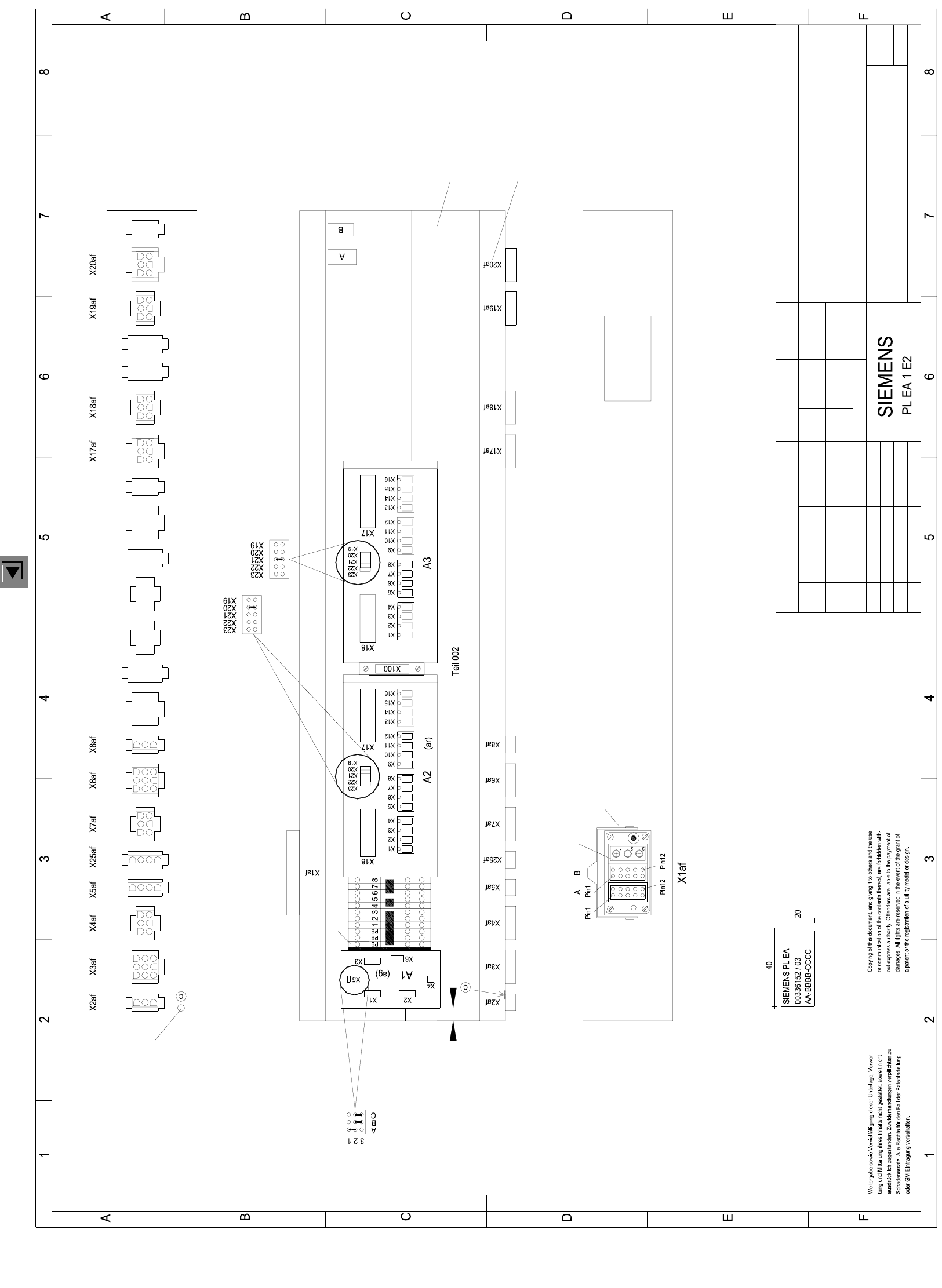
00336152-030103TD3 Distributor, sector 1
03.
01.
Tek
Tek
Tek
10.04.00
21.04.99
21.04.99
Hoffmann14.01.1998
03.
1
A3
1
00336152-030103TD3
10.04.00
4
FSUAUSESFS
Pneumatic module
(Pins 1 and 3 wired)
SMD Placement System SIPLACE HS50
Distributor, Sector 1
CAN input/output module A2 is already hard-wired
Assembly inscription acc. to VA-F-510-001
Font size 2.5mm Material Scotchal 3698-E (Color A1 RAL 9006)
Identification: testing engineer, month, year
C: Ground label ( gn/ye )
The following labels have to be stuck on:
A: Identification label
B: Inspection label
* Note
BBBB = Date (year/month/day) acc. to SN 01007
CCCC = Manufacturer/location acc. to SN 37040
AA = Numeral
Function status
Document status
Product status
but only installed as option !
The "PE terminal block" and the ( 1 2 3 ... ) terminal blocks will be connected with an additional yellow/green jumper.
gn/ye
and 2 grey 3-pole terminal blocks with 2 yellow/green jumpers.
"PE terminal block" made of one yellow/green 3-pole terminal block
Ground hole
Pin1
Pin12
Pin1
Pin12
Module
Bracket
Part 002
Plug designation on edge
Font size 4mm
Part 001
NameStatus Modified Date
Stand.
Check.
Author
Date
Name
(Drawing number)
Main no.
Sheet
Sh.
CAN bus coupler for component table 1
Jumper configuration
SLIO module 3, jumper configuration
SLIO module 4, jumper configuration