SIPLACE D4i 规格说明书英文版.pdf - 第16页
16 PCB Warpage PCB warpage across the directio n of travel max. 1 % of the PCB diagonal, but no t exceeding 2 mm PCB warpage on the co nveyor PCB warpage during placement PCB transport directi on PCB warpage d ownwards, …
15
PCB Conveyor
Technical Data
Single conveyor Flexible dual conveyor Dual conveyor in
Single conveyor mode
Standard dimensions
(length x width)
50 x 50 mm² to
368 x 460 mm²
50 x 50 mm² to
368 x 216 mm²
50 x 50 mm² to
368 x 380 mm²
Wide board
configuration
50 x 50 mm² to
368 x 508 mm²
50 x 50 mm² to
368 x 242 mm²
Long board option 50 x 110 mm² to
610 x 460 mm²
50 x 120 mm² to
610 x 216 mm²
50 x 120 mm² to
610 x 380 mm²
Long board option and
Wide board configuration
50 x 110 mm² to
610 x 508 mm²
50 x 120 mm² to
610 x 242 mm²
PCB thickness Standard 0.3 mm to 4.5 mm (± 0.2 mm) (others available on request)
PCB warpage see page 16
PCB weight max. 3 kg
Clearance on PCB under-
side
25 mm ± 0.2 mm (standard)
max. 40 mm ± 0.2 mm (option)
PCB transport height 830 mm ± 15 mm (standard)
900 mm ± 15 mm (option)
930 mm ± 15 mm (option)
950 mm ± 15 mm (SMEMA option)
Type of interface SMEMA / Siemens
Component-free PCB han-
dling edge
3 mm
PCB changeover time < 2.5 s
PCB positioning accuracy ± 0.5 mm
Flexible dual conveyor Conveyor mode: synchronous or asynchronous
(selected via the software)
Flexible dual conveyor Components to be placed on each conveyor track: same or different
Flexible dual conveyor PCB width on each conveyor track: same or different
Bad fiducial recognition Single conveyor: standard
Synchronous dual conveyor: standard (no global ink spot)
Asynchronous dual conveyor: standard
Automatic electrical width
adjustment
Synchronous dual conveyor: standard
Asynchronous dual conveyor: standard
Manual width adjustment Single conveyor: standard
Fixed conveyor side Right or left
16
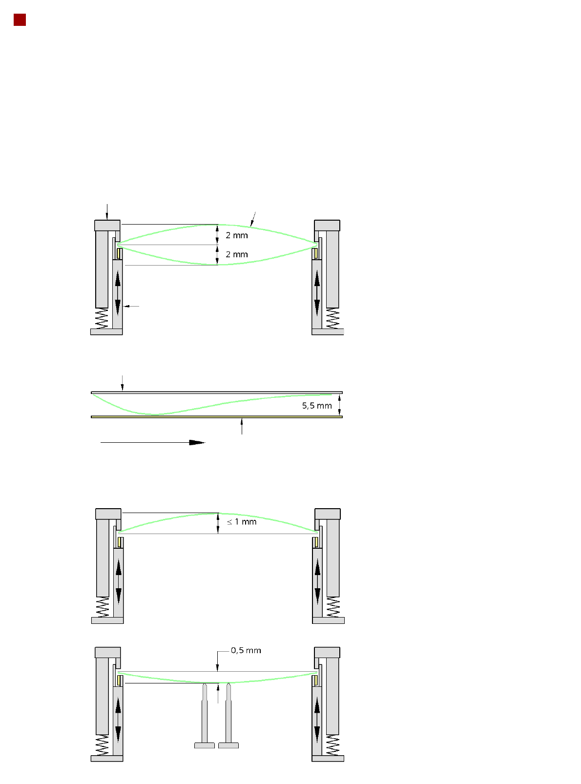
PCB Warpage
PCB warpage across the direction of travel
max. 1 % of the PCB diagonal, but not
exceeding 2 mm
PCB warpage on the conveyor
PCB warpage during placement
PCB transport direction
PCB warpage downwards, max. 0.5 mm
Use magnetic pin supports to achieve this
value.
Conveyor belt
Fixed clamped edge
PCB warpage in direction of travel
+ PCB thickness < 5.5 mm
Fixed clamped edge
Movable clamping device
You should note that the warpage also
reduces the component height.
Magnetic pin support
PCB
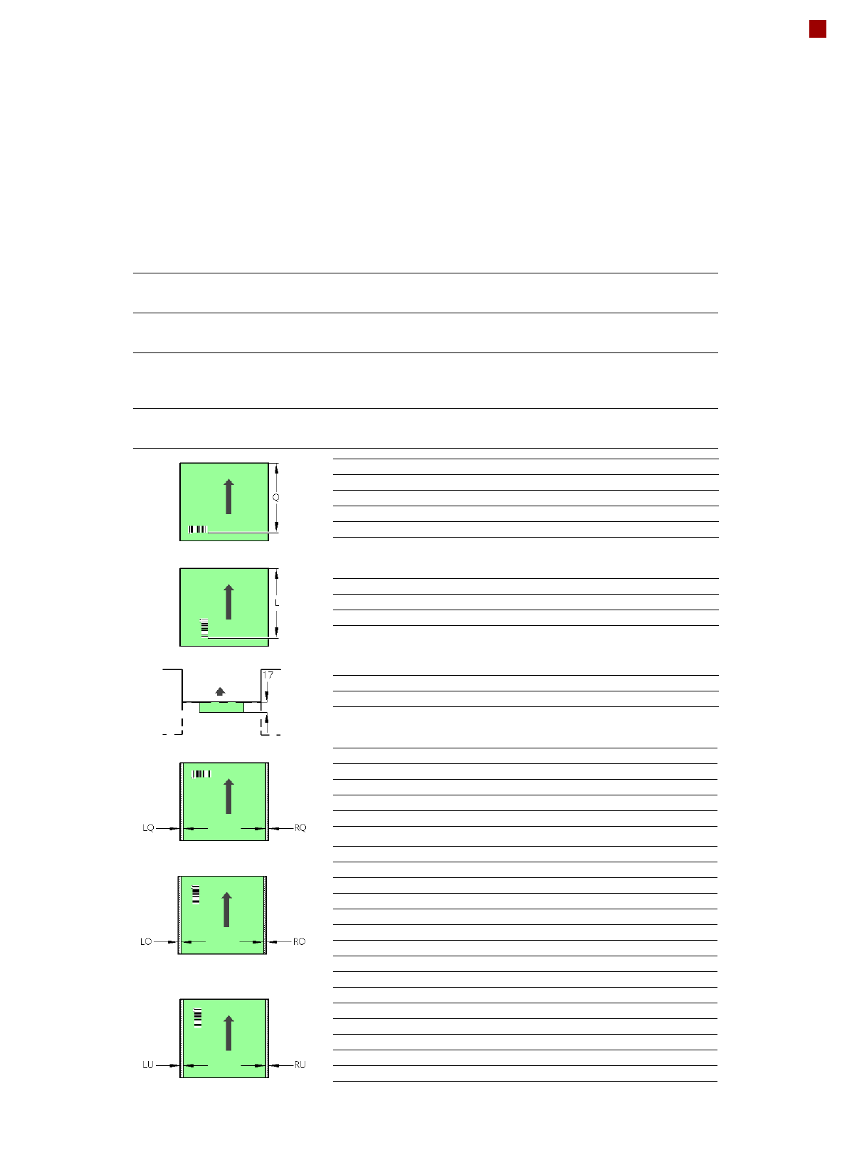
17
PCB Barcode for Product-Controlled
Production (Option)
Label dimensions Stroke width (W): 0.19 < W ≤ 0.3 mm (corresponds to high and medium den-
sity), stroke length: ≥ 4 mm, length of the barcode template window: ≤ 90 mm
Recommended label
colors
Coding: black, dark green, dark blue, background: white, beige, yellow, orange
(contrast ratio > 70% to DIN 66236)
Code types Code 39, Code 128 / EAN 128, Codabar, 2/5 IATA 2/5 industrial, 2/5 inter-
leaved, UPC, EAN, Pharma Code, EAN Addendum (others available on
request), a barcode filter may be defined
Laser scanner safety Laser diode 670 nm (red) / 1.2 mW
Laser protection class 2, degree of protection IP65
Downstream
machine
Upstream
machine
PCB
PCB barcode scanner 1D on top
PCB barcode scanner 1D on bottom
PCB barcode scanner Q [mm]
2D on top 390
1D on top 390
2D on bottom 430
1D on bottom 430
PCB barcode scanner L [mm]
1D on top 320 - 350
1D on bottom 380 - 410
PCB barcode scanner PCB rear projection [mm]
2D on bottom (dual conveyor) 17
PCB barcode scanner LQ [mm] RQ [mm]
2D on top 3 3
1D on top 3 3
2D on bottom 5 5
1D on bottom 5 5
PCB dimensions/conveyor LO [mm] RO [mm]
460 mm SC 3 20
508 mm SC 3 44
216 mm DC1 3 24
242 mm DC1, 430 mm SM1 3 58
216 mm DC2 3 3
242 mm DC2, 430 mm SM2 3 3
PCB dimensions/conveyor LU [mm] RU [mm]
460 mm SC 20 3
508 mm SC 44 3
216 mm DC1 3 3
242 mm DC1, 430 mm SM1 3 3
216 mm DC2 24 3
242 mm DC2, 430 mm SM2 58 3
SC - Single conveyor, DC1/2 - Dual conveyor, track 1/2, SM1/2 - Dual conveyor in Single conveyor mode, track 1/2
If there is a PCB dual conveyor installed on the placement machine, we can provide a special design for
retrofitting the 2D PCB barcode scanner "bottom".