00193915-0202_AI_PSA_ KitZuführmodule8S_DE+EN.pdf - 第27页
PSA Kit for 8/12/16mm S feeder modules 2 A ssembly in structions PSA Kit for 8/12/16mm S feeder modules 12/2006 Edition 27 : Fit the fully assembled base and fi x in place w ith 2 Phillips screws. : Fix the light barrier…
2 Assembly instructions PSA Kit for 8/12/16mm S feeder modules PSA Kit for 8/12/16mm S feeder modules
12/2006 Edition
26
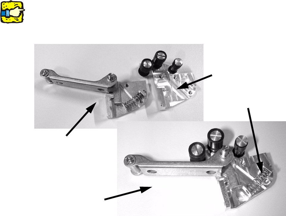
: Remove the spring, the adjusting screw and rocker 1 from the removed base for rocker 1.
: Fit the adjusting screw, rocker 1 and the new spring, type VD 109 (item no.: 00325305-01), in
the new base. You will not need the original spring again.
2
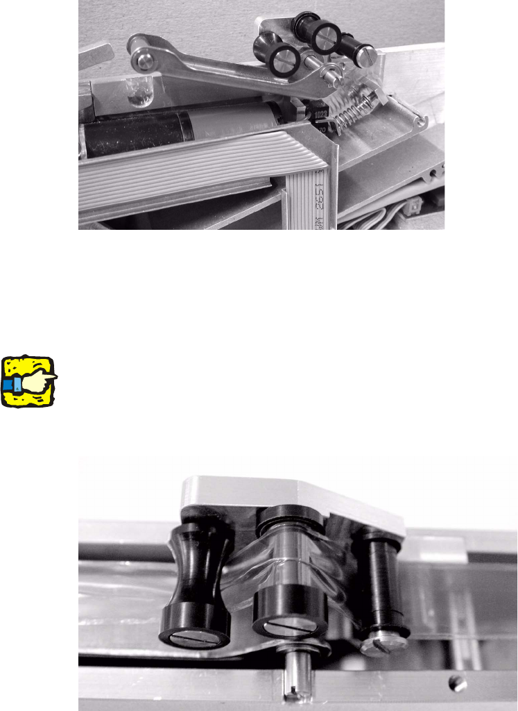
Set the adjusting screw to the lowest spring tension. 2
2
2
2
2
2
2
2
2
2
2
2
2
2
New base for rocker 1
Fully assembled
new base for rocker 1
Spring, adjusting screw
and rocker 1 on the old
New spring, type VD 109
PSA Kit for 8/12/16mm S feeder modules 2 Assembly instructions PSA Kit for 8/12/16mm S feeder modules
12/2006 Edition
27
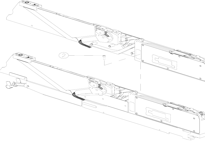
: Fit the fully assembled base and fix in place with 2 Phillips screws.
: Fix the light barrier (1 hexagon socket head screw).
: Refit the top tape channel (1 Phillips screw).
: Reattach the cable cover with the ribbon cable.
2
: Screw on the backing plate once more (5 Phillips screws).
: Fit the pick-up window and the cover strip take-up edge (2 slotted-head screws).
: Screw on the lock (1 Phillips screw).
Adjust the lock so that the window flap can move freely 0.02 to 0.05 mm in the vertical direction.
2
Do not loosen the top Phillips screw on the lock. This is glued in place. 2
2
: The cover strip must be clamped as shown:
2
2 Assembly instructions PSA Kit for 8/12/16mm S feeder modules PSA Kit for 8/12/16mm S feeder modules
12/2006 Edition
28
2.5 Feeder module 2x8 mm
2.5.1 Detaching the conveyor tracks
To carry out the retrofit on the right-hand track (viewed in the tape direction of travel) of the
2x8 mm feeder module, you must first detach the right-hand track from the base element (left-
hand track). 2
2
: Loosen the cable cover (2) so that the seals in the cable gland to the base element can be re-
moved.
Cable cover "2" is only accessible from the right-hand side of the module. The wiring will be
damaged if you do not remove these seals first.
2
Abb. 2.11 - 1 Remove the right-hand feeder module (track) from the base element.
M2.5 hexagon socket head screw
3 M2.5 hexagon socket head screw
4 Right-hand track
2