00193915-0202_AI_PSA_ KitZuführmodule8S_DE+EN.pdf - 第28页
2 Assembly instructions PSA Kit for 8/12/16mm S feeder modules PSA Kit for 8/12/16mm S feeder modules 12/2006 Edition 28 2.5 Feeder module 2x8 mm 2.5.1 Det aching the conveyor tracks T o carry out the retro fit on the ri…
PSA Kit for 8/12/16mm S feeder modules 2 Assembly instructions PSA Kit for 8/12/16mm S feeder modules
12/2006 Edition
27
: Fit the fully assembled base and fix in place with 2 Phillips screws.
: Fix the light barrier (1 hexagon socket head screw).
: Refit the top tape channel (1 Phillips screw).
: Reattach the cable cover with the ribbon cable.
2
: Screw on the backing plate once more (5 Phillips screws).
: Fit the pick-up window and the cover strip take-up edge (2 slotted-head screws).
: Screw on the lock (1 Phillips screw).
Adjust the lock so that the window flap can move freely 0.02 to 0.05 mm in the vertical direction.
2
Do not loosen the top Phillips screw on the lock. This is glued in place. 2
2
: The cover strip must be clamped as shown:
2
2 Assembly instructions PSA Kit for 8/12/16mm S feeder modules PSA Kit for 8/12/16mm S feeder modules
12/2006 Edition
28
2.5 Feeder module 2x8 mm
2.5.1 Detaching the conveyor tracks
To carry out the retrofit on the right-hand track (viewed in the tape direction of travel) of the
2x8 mm feeder module, you must first detach the right-hand track from the base element (left-
hand track). 2
2
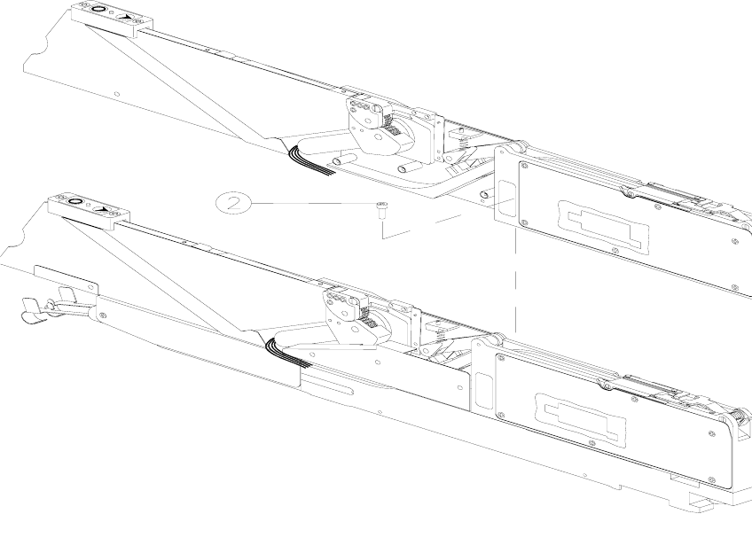
: Loosen the cable cover (2) so that the seals in the cable gland to the base element can be re-
moved.
Cable cover "2" is only accessible from the right-hand side of the module. The wiring will be
damaged if you do not remove these seals first.
2
Abb. 2.11 - 1 Remove the right-hand feeder module (track) from the base element.
M2.5 hexagon socket head screw
3 M2.5 hexagon socket head screw
4 Right-hand track
2
PSA Kit for 8/12/16mm S feeder modules 2 Assembly instructions PSA Kit for 8/12/16mm S feeder modules
12/2006 Edition
29
: Before lifting the right-hand feeder module, remove the two foam cubes in the rear cut-out (they
can be seen after the cable cover (2) is removed).
: Hexagon socket head screw M 2.5 from the underside of the base element (3).
: Hexagon socket head screw M 2.5 in the cut-out in the right-hand feeder module (2).
: Raise the right-hand feeder module vertically until it comes away from the locating pins in the
base element (5). Do not pull the cables, otherwise the plug-in connectors on the board may
come away.
: Carefully tilt the removed feeder module with the side surface facing outwards so that it lies
lengthwise beside the base element.
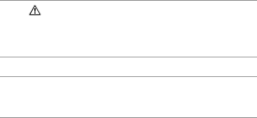
CAUTION
Do not detach the drawer unit in the base element. The cable connections from the feeder module
to this drawer unit are long enough if you carefully tilt the feeder module outwards during removal
and place it beside the base element.
Do not pull the cables as you do this. 2
NOTE
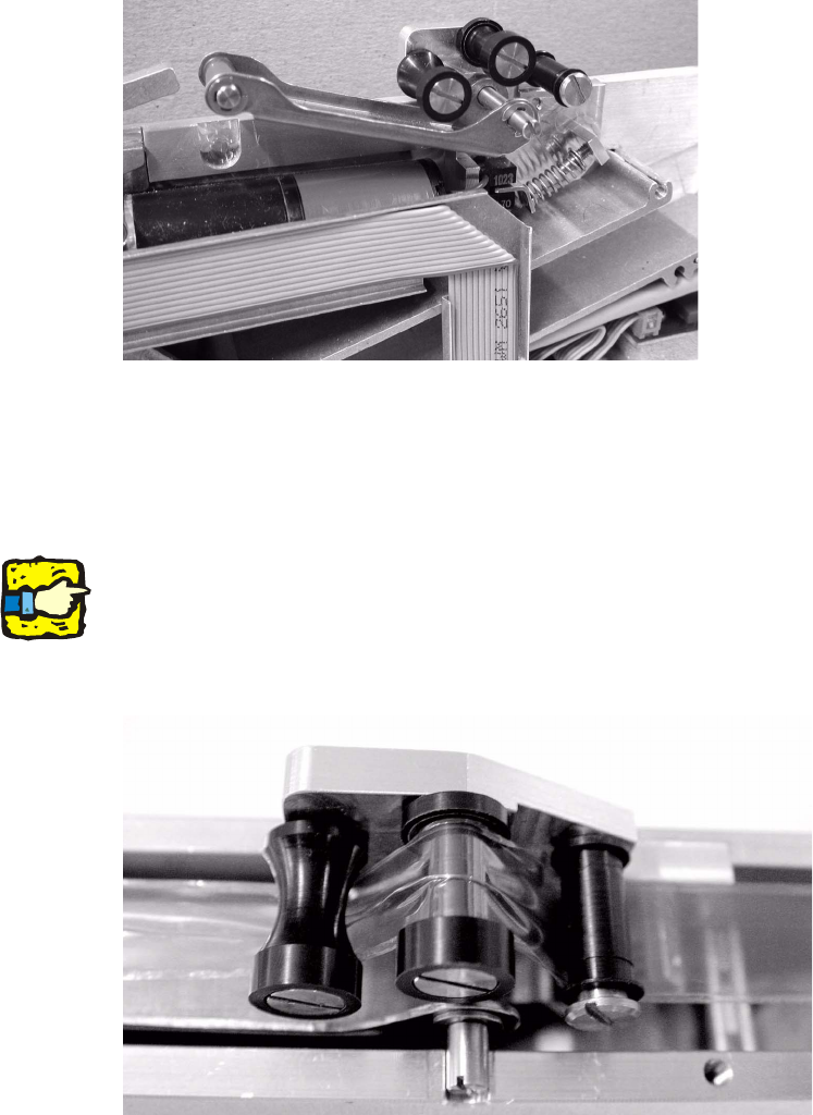
If you have opened the right-hand side panel, it is a good idea to grease the stop, the pinion and
the outer circumference of the worm (1-3) sparingly with Isoflex Topas L30 (item no. 00303140-
01). 2
2
2
2
2
2
2
2
2
2
2
2