cp45头部故障判断.pdf - 第19页
1. Head Module Ver. Date CP45 CP45NEO 00 2004/11 O O 1-1 Refer Fig 1-9-4 for the Position to M easure Belt Tension * Adjustments after this w ork - Head(Fly) Camera Calibration.(Ref. 2-3) - Head offset Setting.(Ref. 2-16…
1. Head Module
Ver. Date CP45
CP45NEO
00 2004/11 O O
1-1
1-9. Z-axis Motor/Timing Belt Replacement, Check
*Tools
a) Wrench
*Part
a) TIMING BELT [340-2GT-12] (J6602023A)
b) Z-axis Motor
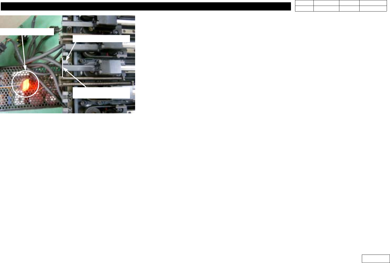
1) In Case the Fixture to Find Servo Motor Z-Phase is Not Available, Indicate the Position of Motor
Z-PhaseatHeadFrameBeforeSeparatingMotortobeReplaced(Ref.Fig1-9-1-1)
- Lift the Z-axis to the Position Z-Home Sensor Senses (Ref. (1))
- Check the Z-Phase Mark of Z-Motor to be Replaced (Ref. (2))
-MarkatHeadBodyintheSameDirection(Ref.(3))
- Assembly of Z-Phase of New Z-Motor to the Same Position This Way Enables the Replacement
w/o Checking Z-Phase Additionally
2) Loosen the Bolt Fastened at Upper Head#1,3,5 Motor(Check Bolt Specification), and Separate Motor
3) Assemble New Motor(Ref. Fig 1-9-3), and Fix Belt at Pulley at This Time
(Check the Position of Z-Phase to Assemble in the Opposite Direction of 'Procedure 1)')
4) (In Case Z-Phase Detecting Fixture is Available)Use Detecting Fixture to Assemble Motor Z-Phase
so that Z-axis Home Sensor can be On Right After the Detection of Motor Z-Phase
(Ref. Fig 1-9-1)
=> After the Encoder Cable of Motor is Connected, Z-Phase is Detected When the Lamp of Fixture
is On as Running Motor
5) For Lower Head#2,#4,#6, FV and Swing Motor and Adjacent Pulley Should be Separated First to
Separate Motor
6) After This, Replacement Procedure is Same(Ref. Fig 1-9-2 for Sub Assembly of Motor)
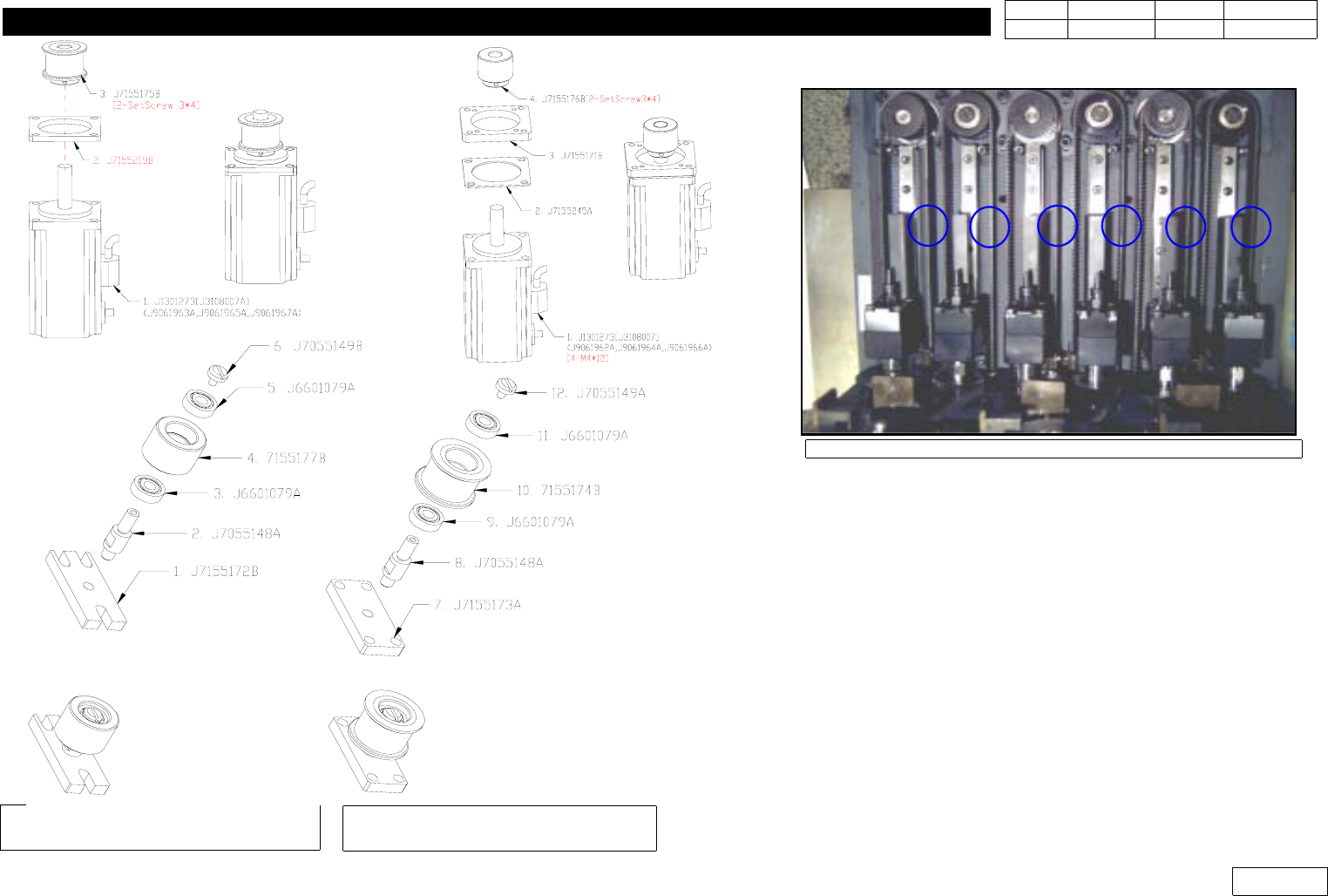
7) Refer Adjacent Z-axis Belt of Head to Adjust the Tension of Z-axis Belt
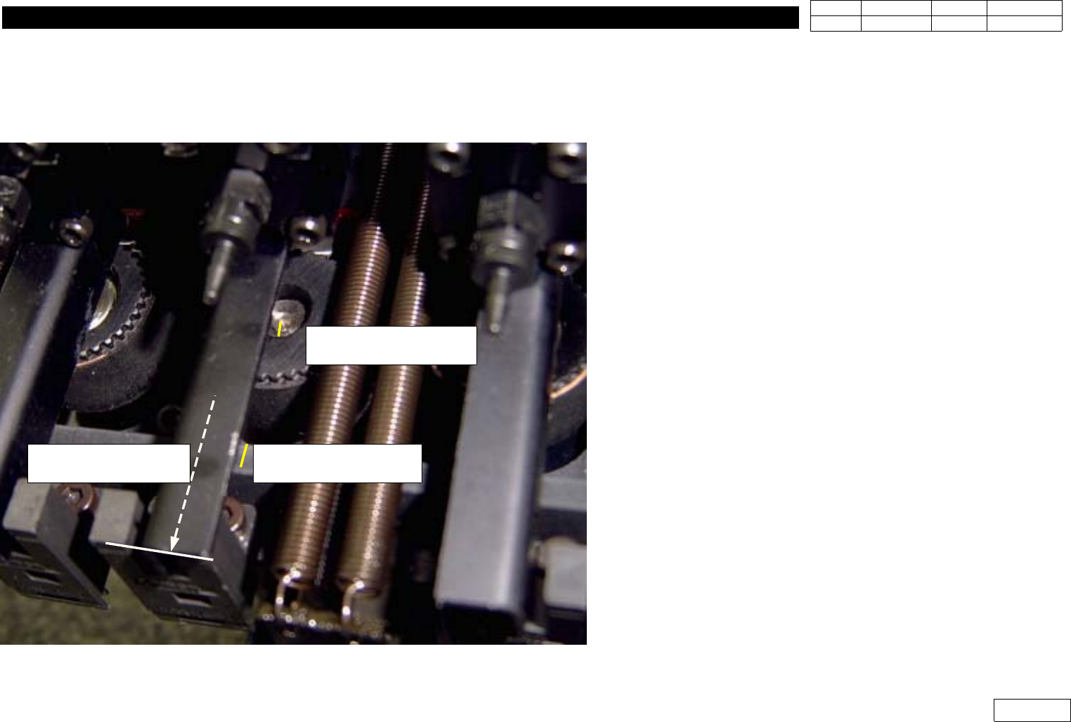
Fig.1-9-1 Detacting Z-Phase and
the position of Z-Home dog
Z Axis Home Sensor
When detect Z-Phase,
that time the position
of Z- home Dog
1. Head Module
Ver. Date CP45
CP45NEO
00 2004/11 O O
1-1
Refer Fig 1-9-4 for the Position to Measure Belt Tension
* Adjustments after this work
- Head(Fly) Camera Calibration.(Ref. 2-3)
- Head offset Setting.(Ref. 2-16)
(1) Push the Z-axis upper
position to detect the sensor
(2) Check the Z-Phase mark
on the motor shaft.
(3) Mark the Z-Phase on the
Head body
Fig.1-9-1-1 Z-phase mark procedure for the Z-Motor.
1. Head Module
Ver. Date CP45
CP45NEO
00 2004/11 O O
1-1
Fig1-9-2 HEAD *2 4 6 Z-Motor and
Z-Pulley sub-assembly
Fig1-9-3 HEAD *1 3 5 Z-Motor and
Z-Pulley Sub Assembly
Fig1-9-4 Position for Z-Axis Belt tension
Note) Part Number is Displayed for CP45NEO Use,
and Motor is Different from CP45F(V)