cp45头部故障判断.pdf - 第6页
1. Head Module Ver. Date CP45 CP45NEO 00 2004/11 O O 1-1 1-1.Flying Vision Replacement Procedure *T o o l s a) Screw Driver(+ Small) b) Hex Wrench( 3mm) *P a r t s a) Flying Vision (25mm: J9059032B, 15 mm:J9059060B) 1) T…
1. Head Module
Ver. Date CP45
CP45NEO
00 2004/11 O O
1-1
Trouble Shooting Guide
No. Bad Items Possible Cause Action
23 Excessive Foreign Substance
Dump Ratio
Part Data Error Re-check Part Data and Adjust Tolerance Value
Bad Z-axis Height Setting Resetting(Ref. 1-18 Z-axis Height Check)
Blow Setting Error Resetting(Ref. 1-14 Blow Setting Check)
Blow Setting Error Resetting(Ref. 1-14 Blow Setting Check)
Bad Sol Valve of Air Distributor Resetting(Ref. 1-14 Blow Setting Check)
Check Install Part(Part Data) Re-check Part Data and Adjust Tolerance Value
Mirror Foreign Substance, Damage Clean Mirror, Replace if Damaged(Ref. 1-4 Mirror Setting Procedure)
Bad Z-axis Height Setting Resetting(Ref. 1-18 Z-axis Height Check)
Bad Head-Move Camera Offset Calibration(Ref. 1-17 Move Camera Offset Setting)
Check Mounter Offset Calculate and Input Mounter Offset
Mirror Foreign Substance, Damage Clean Mirror, Replace if Damaged(Ref. 1-4 Mirror Setting Procedure)
Bad Sol Valve of Air Distributor Resetting(Ref. 1-14 Blow Setting Check)
Bad Head-Move Camera Offset Calibration(Ref. 1-17 Move Camera Offset Setting)
28 Collision btw. Nozzle and Head Copy Part.mdb in CP45F(V) and Use it in
CP45NEO w/o Using 'Merge' Function
(Occurs in CP45F(V) Nozzle : 9.4,
CP45NEO Nozzle : 13.5)
Select Nozzle in F11(Device) of Sys.setup
=> Select Nozzle in Device List
=> Check Length of Nozzle Dimension(All Nozzles)
=> CP45F(V) : 9.4, CP45NEO : Change to 13.5
26 Bad Installment-Chip
24 Bad Installment-Crushed Lead
25 Bad Installment-
Angle(Twisted)
1. Head Module
Ver. Date CP45
CP45NEO
00 2004/11 O O
1-1
1-1.Flying Vision Replacement Procedure
*Tools
a) Screw Driver(+ Small)
b) Hex Wrench( 3mm)
*Parts
a) Flying Vision (25mm:J9059032B, 15mm:J9059060B)
1) Turn Off Power of Equipment
2) Separate Flying Vision
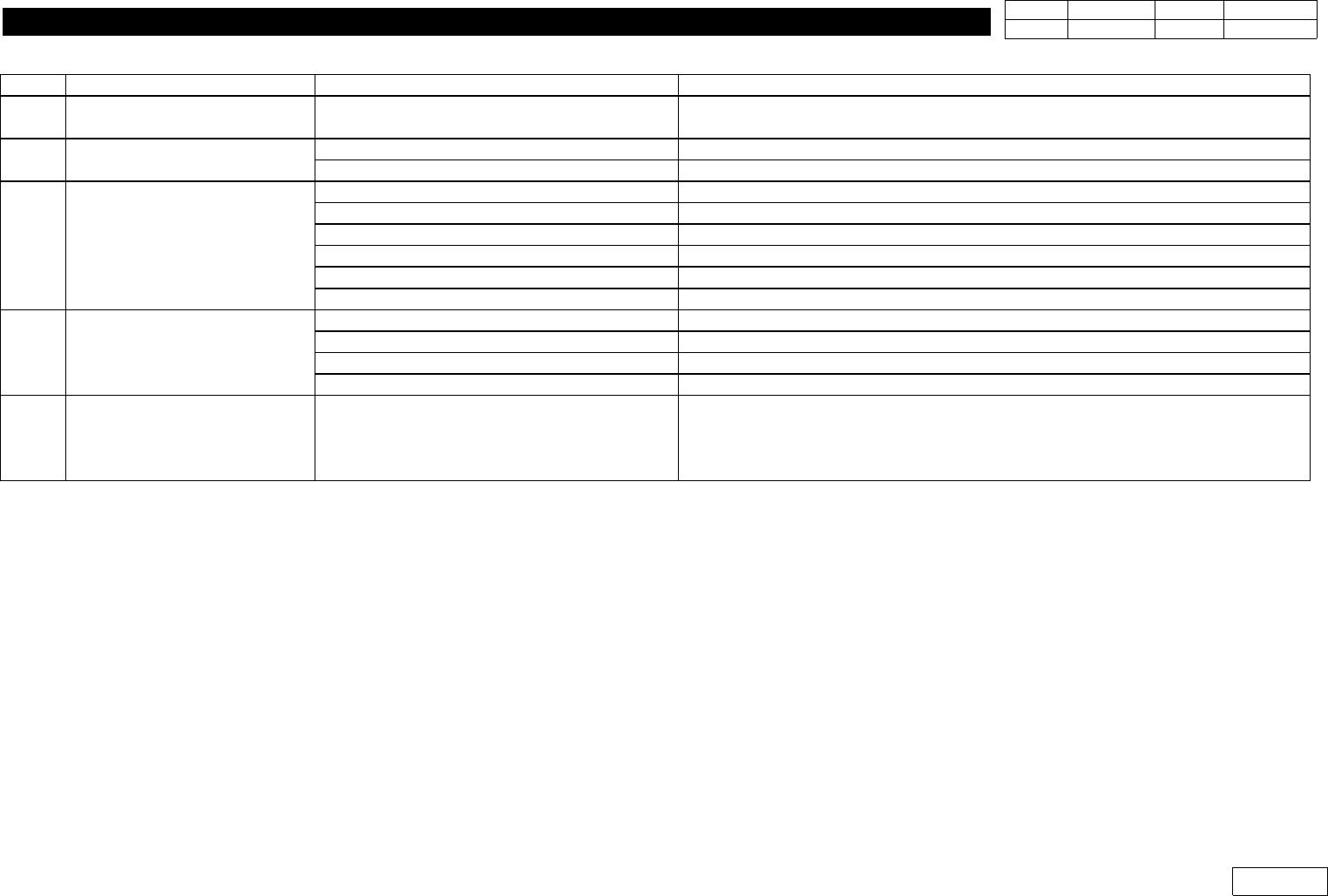
- Separate Bolt 4EA, Connector(for Outer Light) (Ref. Fig.1-1-1)
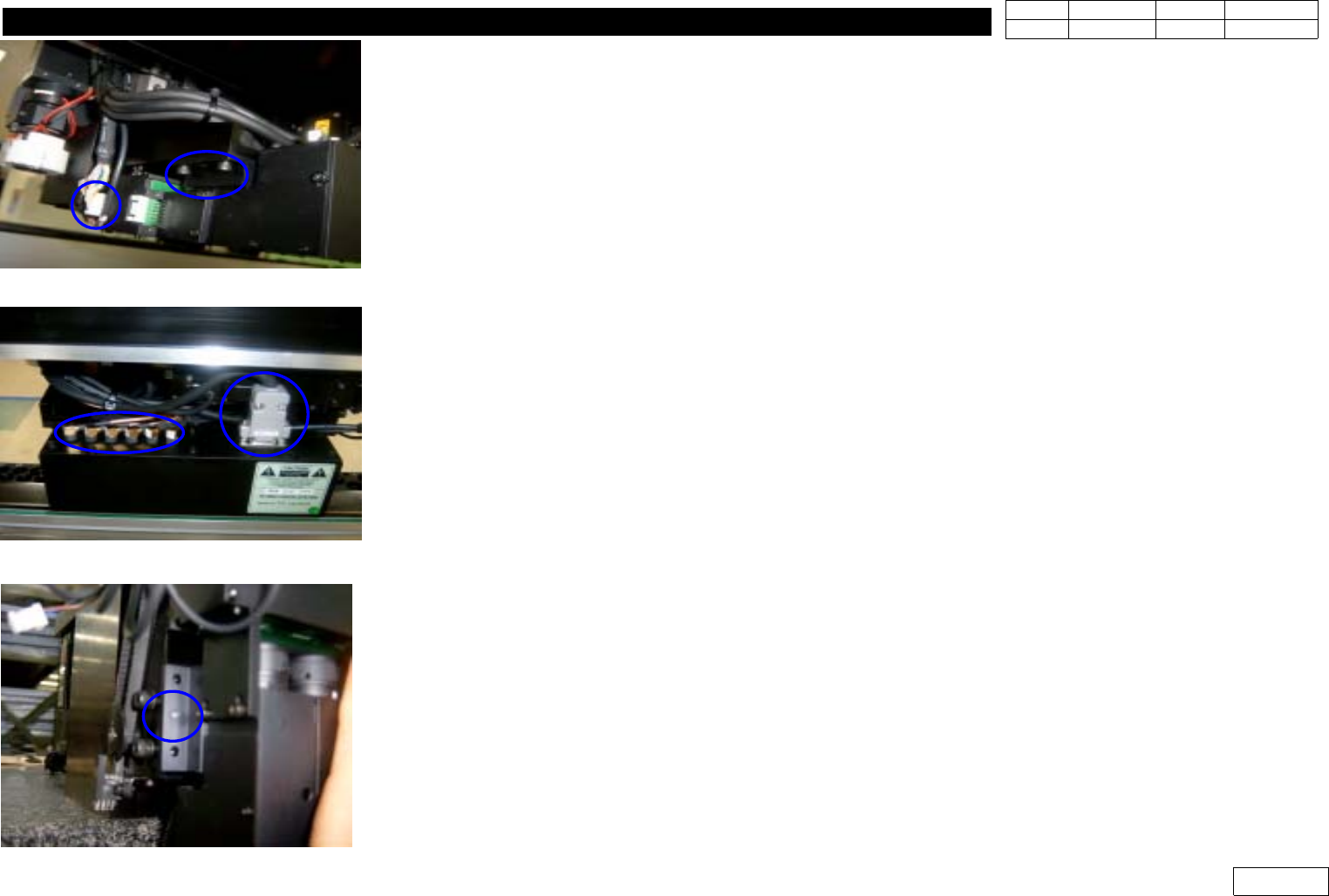
- Separate FV Data Cable Connector(6EA), D-Sub Connector (Ref. Fig 1-1-2)
3) Assemble Flying Vision
- First Assemble D-sub connector to Flying Vision and Fasten it with Screw
- Assemble Flying Camera with Precision in Fitting Pin of Camera Bracket (Ref. Fig.1-1-3)
- Fasten Flying Vision with Bolt 4EA
- Assemble FV Data Cable Connector and Connector(for Outer Light)
(Caution : Note the Order of Data Cable from 1 to 6)
* Adjustments after this Work
- Proceed Head(Fly) Camera Calibration (Ref. 1-2)
- Proceed Head-Fly Offset to Compensate Offset btw. Camera Center of FV and Spindle Center
(Ref. 1-3)
- Proceed Vision Nozzle Check (Ref. 1-12)
- Check Mount Offset
Fig.1-1-1 Flying Vision (Bolt,connector)
Fig.1-1-2 Flying Camera
(D-sub Conn. Data Cable
Fig.1-1-3 Pin for Flyiing Vision assembly
1. Head Module
Ver. Date CP45
CP45NEO
00 2004/11 O O
1-1
1-2.Head(Fly) Camera Calibration
*Tools
a) Hex Wrench( 2.5mm)
b) Fly Camera calibration Tool
*Parts
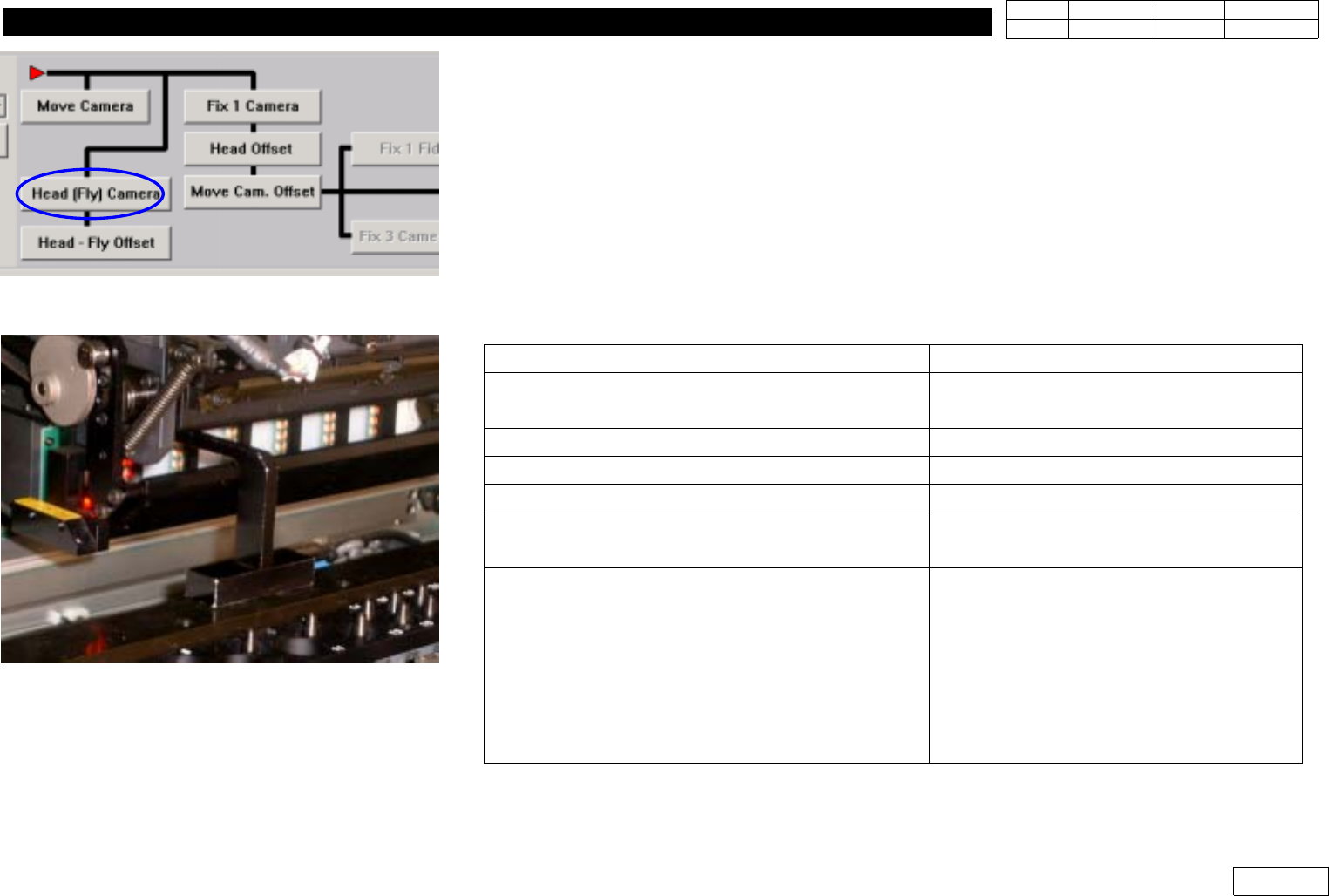
1] Menu : Select Sys. seup => Camera => Calibration =>Head(Fly) Camera (Ref. Fig 1.2.1)
2) Remove Mirror Cover of Head Module
3) Remove Nozzle of Head ('Put all Nozzle')
4) Click 'Head(Fly) Camera' to Display Messages Below. Proceed in Order
Message
Procedure
First, we must put all nozzles from heads
manually To moving down Z Axis,click[hear]
Check if There is No Nozzle and Click
'Next' =>(Caution) Mirror Moves to 45'
'Z axis moving down Please wait for a minute'
Stand by Until Next Message
'Next, Mirror will close. To close, click [Next]'
Click 'Next'
'Moving now,Please wait for a moment'
Stand by Until Next Message
'Setting the fly camera calibration tool on
conveyor finished, then click[Next] for next step'
Install Calibration Tool as Fig.1.2.2 and
Click 'Next'
'Adjust between vision screen center to mark
center by jogbox [head 1 Camera]
To calibratation, Click [Next]
Using Jogbox, Make the Center of Head1
Camera(Center of Vision Monitor) Coincide
with the Center of Calibration Tool and
Click 'Next' (Ref. Fig.1-2-3) => Camera of
Head1 is Calibrated and the Output
(Previous and Present Value) is Printed
Fig.1-2-1 Head(Fly) Camera Calibration.
Fig.1-2-2 Install calibration tool on the C/V