Horizon APiX Appendix Manual-low res.pdf - 第35页
INSTALLATION APPENDIX PRE POWER UP CHE CKS 2.16 Appendix to Micron Technical Manuals Chapter Issue 1 June 15 7. Connect the two probes of a digit al volt meter (DVM) together and ensure that the DVM is reading 0 Ω . 8. M…
INSTALLATION APPENDIX
PRE POWER UP CHECKS
Chapter Issue 1 June 15 Appendix to Micron Technical Manuals 2.15
PRE POWER UP CHECKS
Having removed the transit brackets and assembled the machine, prepare to
install the machine, as follows:
Electrical Test Before the machine is connected to the factory electrical supply, the following
electrical tests must be performed:
1. Ensure the mains isolator switch is in the OFF position.
2. Remove the Front Panel of the machine to gain access to the mains isolator
switch.
3. Remove the front cover of the mains isolator switch.
4. Loosen the two blue coloured terminal cover securing screws and remove
the cover.
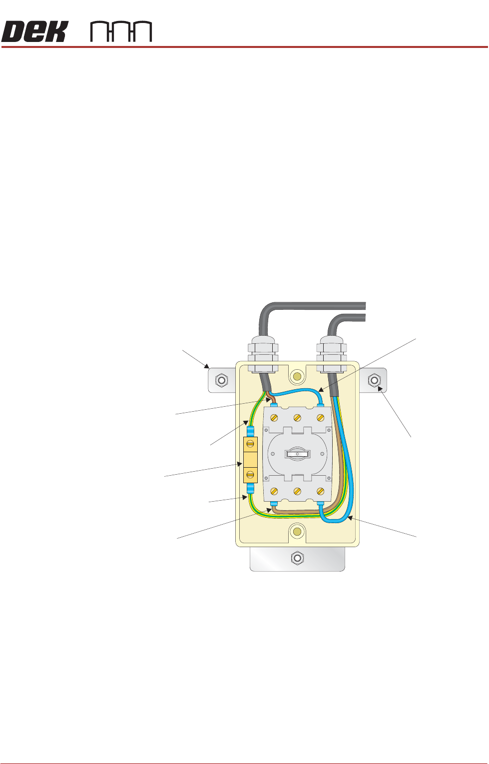
5. Perform a visual inspection of the mains isolator switch ensuring the follow-
ing:
a. The earth input and earth output cables are connected to the earth tag.
b. The live input is connected to the top of the isolator switch on the left hand
side.
c. The live output is connected to the bottom of the isolator switch on the left
hand side.
d. The neutral input is connected to the top of the isolator switch on the right
hand side.
e. The neutral output is connected to the bottom of the isolator switch on the
right hand side.
6. Ensure that all seven cables are secure and no bare wires are showing.
Neutral (Blue)
Input
Isolator Mount
Securing Nut
(in 3 positions)
Isolator Mount
Live (Brown)
Input
Earth (Green/Yellow)
Input
Earth (Green/Yellow)
Output
Earth Tag
Live (Brown)
Output
Neutral (Blue)
Output

INSTALLATION APPENDIX
PRE POWER UP CHECKS
2.16 Appendix to Micron Technical Manuals Chapter Issue 1 June 15
7. Connect the two probes of a digital volt meter (DVM) together and ensure
that the DVM is reading 0Ω.
8. Measure the resistance between the earth tag and all three isolator mount
securing screws ensuring that all measurements are less than 0.5Ω.
9. Remove the Rear Panel of the machine.
10.Measure the resistance between the following points ensuring that all
measurements are less than 0.5Ω:
a. PC earth stud and a securing screw that secures the PC to the machine
frame.
b. M36 earth stud and a securing screw that secures the M36 to the machine
frame.
c. M37 earth stud and a securing screw that secures the M37 to the machine
frame.
d. M39 earth stud and a securing screw that secures the M39 to the machine
frame.
11. Refit the Rear Panel.
12.Refit the terminal cover.
13.Refit the mains isolator cover.
14.Refit the Front Panel.

Appendix to Micron Technical Manuals
APPENDIX C
Technical Reference
Information