Horizon APiX Appendix Manual-low res.pdf - 第67页
TECHNICAL REFERENCE APPENDIX CALIBRATIONS 3.30 Appendix to Micron Technical Manuals Chapter Issue 1 June 15 CALIBRA TIONS Squeegee Module Squeegee Pressure Calibration Squeegee pressure calibration is carried out on mach…
TECHNICAL REFERENCE APPENDIX
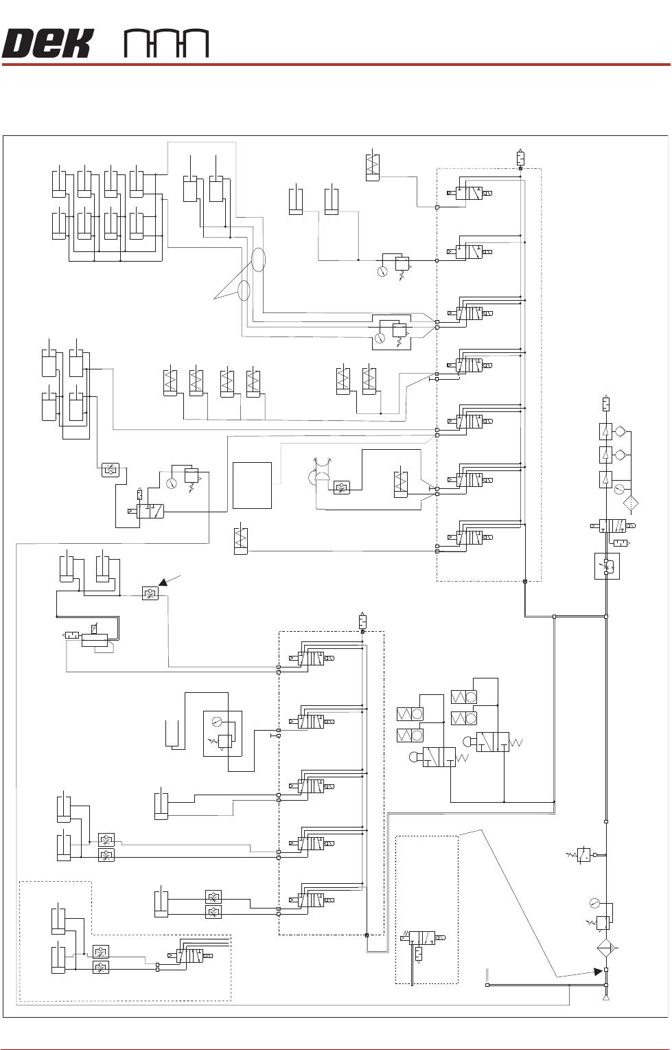
PNEUMATIC SCHEMATICS
Chapter Issue 1 June 15 Appendix to Micron Technical Manuals 3.29
PNEUMATIC SCHEMATICS
Figure 3-5 Pneumatic Schematic Sheet 1
To Grid-Lok Tooling
See Board Support
Tooling Chapter
Pneumatic Dump
Valve. Only fitted
to machines
with M39 EMO.
5/2
9SOL29
5/2
9SOL28
5/2
9SOL27
5/2
9SOL25
Screen Load
Actuator
A
B
ASM Rail Lock
Rail Clamps
Left
Rail Clamps
Right
Out
Paste Dispense
In
Reg/Assy
IN
P
Out
R
Vacuum
Tooling
Venturi Vacuum Tooling (optional)
Pressure
Sense
Filter/Reg Assy
Mains
Air In
At 4.5 Bar
Minimum
3/2 Dual
16SOL31A
5/2
16SOL08
5/2
16SOL07
5/2
16SOL03
5/2
16SOL10
5/2
16SOL14
A
B
A
B
A
B
A
B
A
B
A
Lid Bolt
RTC Vane Clamp
Lift Sol/
Heavy Palete Rails
Snugger
ProFlow ATx Only
3/2 Dual
16SOL31B
B
5/2
9SOL26
A
B
Chase Clamps
Only one
connection
depending on type
'C' Chase/ASM
Screen Clamps
Standard - 8 Clamps
Machined C Chase - 4 Clamps
ASM Screen Clamps
Screen Clean
Squeegee Bar
(optional)
Proclean
Screen Clean
Squeegee Bar
(optional)
Board Clamps
Grid-Lok
Control
Unit
Machine Rear Solenoids
A
B
A
B
A
B
Print Carriage Solenoids
Auto Drip Tray
Paste Dispense
Tilt
ProFlow + SCAR
(optional)
5/2
9SOL28/29
A
B
Semi Auto Screen Load/
Screen Load Actuator
Board Clamp
Reg (optional)
In Out
Camera
Board Stop
Remote Board
Stop
TECHNICAL REFERENCE APPENDIX
CALIBRATIONS
3.30 Appendix to Micron Technical Manuals Chapter Issue 1 June 15
CALIBRATIONS
Squeegee Module
Squeegee Pressure
Calibration
Squeegee pressure calibration is carried out on machines after the following
circumstances:
• The squeegee mechanism is replaced
• The strain gauge bridge in the squeegee mechanism is replaced
• The rising table sensors have been replaced or adjusted
A force meter calibration jig and squeegee pressure plate are required to
perform the squeegee pressure calibration.
NOTE
1. Ensure that the rising table print reference height is set correctly before
commencing, (the calibration relies upon accurate positioning of the table to
make a reference).
2. Ensure that the Pressure Hardware parameter in Maintenance\Machine
Setup\Options is set to FITTED.
Use the following procedure to calibrate the squeegee pressure:
WARNING
BOARD CLAMPS. EXTREME CARE MUST BE EXERCISED WHEN WORKING IN
THE TOOLING AREA OF THE MACHINE TO AVOID INJURY. THE FOILS ON THE
FRONT AND REAR BOARD CLAMPS ARE VERY SHARP.
1. From the Ready page, select Unload Screen.
2. Open the front printhead cover.
3. Remove the screen from the machine.
4. Remove the tooling (if fitted) from the manual tooling plate.
5. Close the front printhead cover.
6. Press the System button.
7. Select Maintenance.
8. Select Calibrations.
9. Select Pressure.
10.Select Calibrate Readings.
The rails are checked for the presence of a board, the print carriage moves
to the calibration position, the rear rail moves to home position, the table
homes and the board clamps are closed.
11. The machine cover is unlocked and the message ‘Fit the pressure calibra-
tion rig’ is displayed with the following window:
12.Open the front printhead cover.
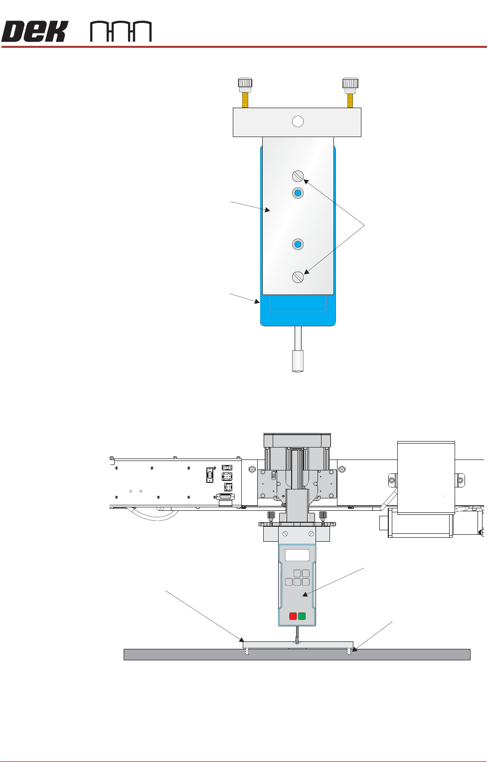
13.Ensure that the calibration jig is secured to the mounting plate as shown in
SEMI 2
CALIBRATION DATA
Gain Factor
1.02
TECHNICAL REFERENCE APPENDIX
CALIBRATIONS
Chapter Issue 1 June 15 Appendix to Micron Technical Manuals 3.31
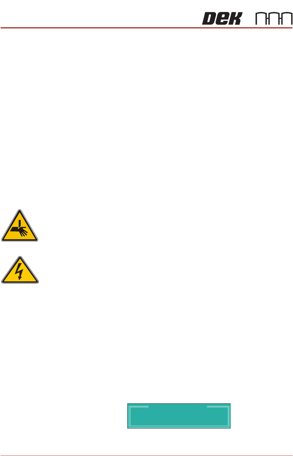
the following graphic:
14.Fit the calibration jig to the front squeegee position.
15. Fit the squeegee pressure plate to the rising table ensuring that the locating
dowels insert the holes of the rising table.
Mounting Plate
Mounting Holes
Calibration Jig
A
A
S
S
View on Front Squeegee MechanismUnderneath Rising Table and
View on Front of Rising Table and Squeegee Mechanism
Squeegee Pressure Plate
Locating Dowel
(in 2 positions)
O
OFF
I
ON
UNITS
Zero
MAX TXD
RESET
00.00
Portable Force Gauge
(Calibration Jig)