EUKYX-199-5100_G5S2_Instruction_Vol5_E.pdf - 第81页
EUKYX 2-9 199-5100 1.9 Head Section Layout (Connector Box Section) 1. 9 Head Section L ay out ( Connector Bo x Sec tion ) Y0707 Y0707 Y0707 Symbol Name Symbol Name Y0707 Air Blow V alve
EUKYX
2-8199-5100
1.8 Head Section Layout (General View)
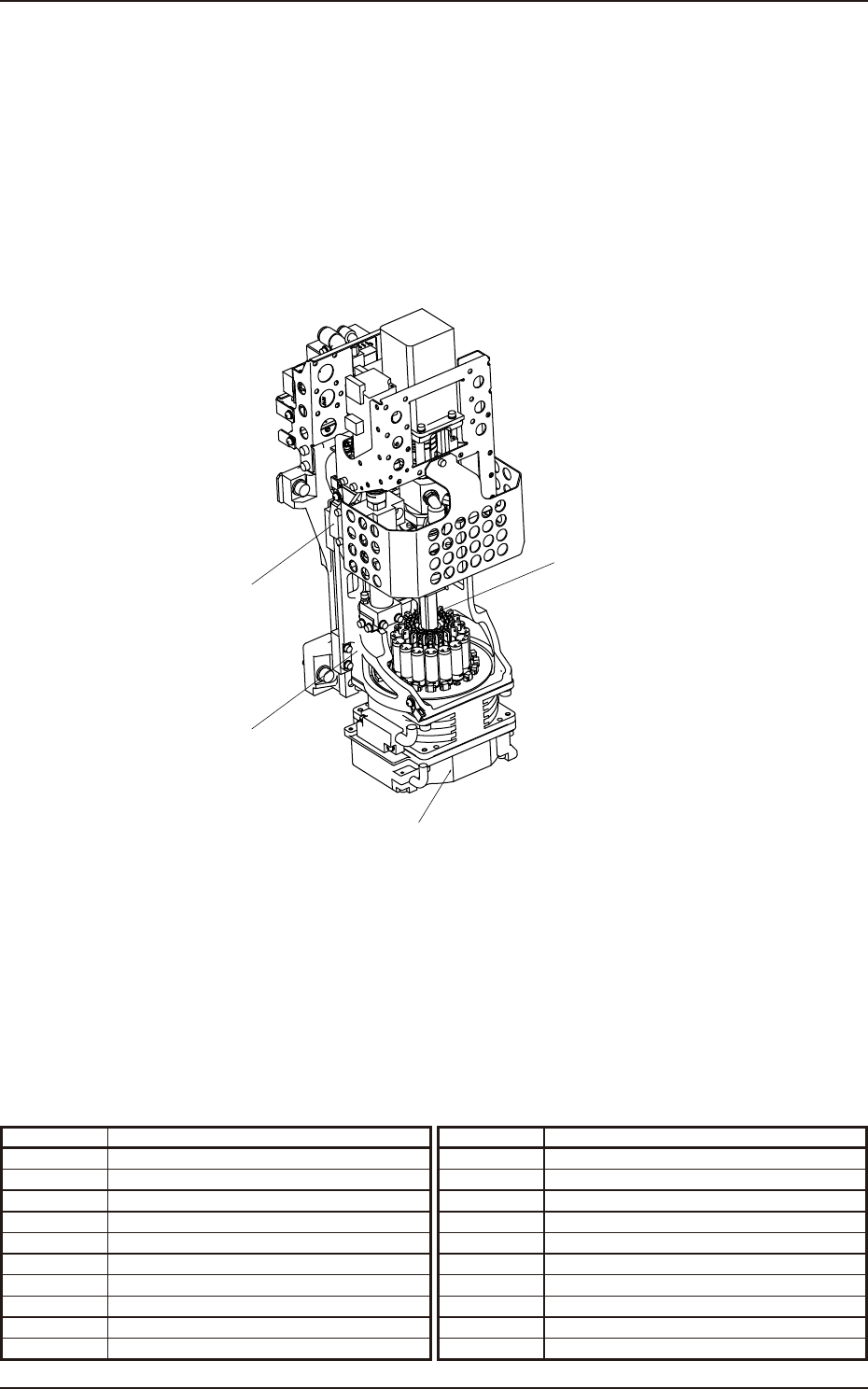
1.8 Head Section Layout (General View)
Symbol Name Symbol Name
Head Rotation Section
Nozzle U/D Section
Nozzle Selection Section
Head U/D Section
EUKYX
2-9199-5100
1.9 Head Section Layout (Connector Box Section)
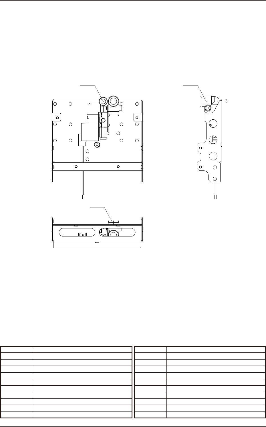
1.9 Head Section Layout (Connector Box Section)
Y0707 Y0707
Y0707
Symbol Name Symbol Name
Y0707 Air Blow Valve
EUKYX
2-10199-5100
1.10 Head Section Layout (Head Rotation Section)
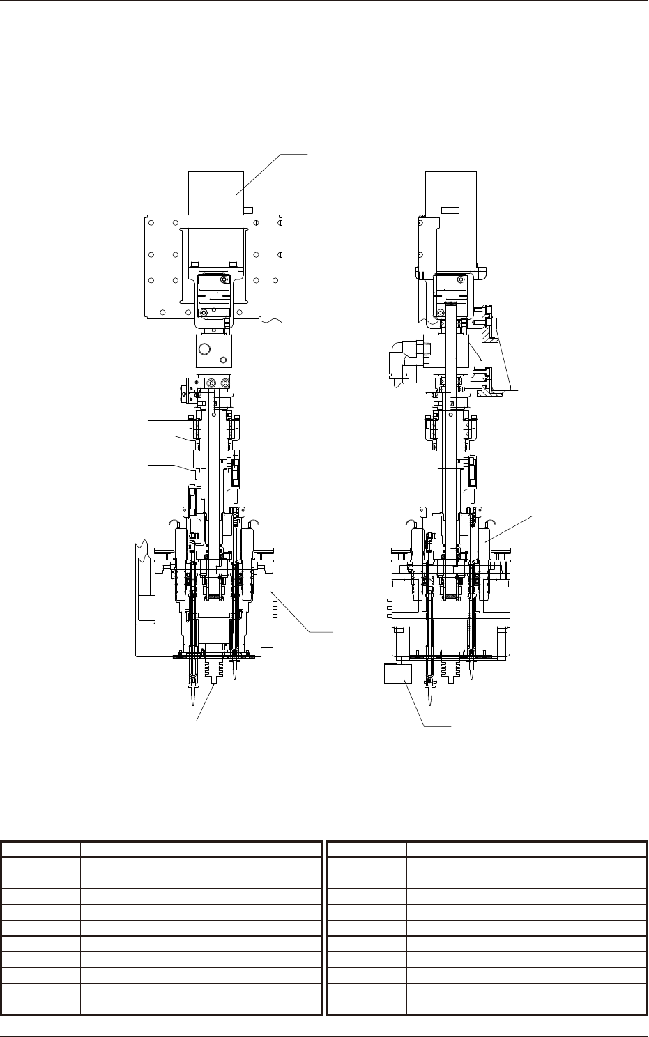
1.10 Head Section Layout (Head Rotation Section)
U37
Y0601-Y0615
U03
M31
U04
1.6x6
1.6x3
1.6x3
1.6x4 1.6x41.6x4 1.6x4
1.6x4
1.6x3 1.6x3
2x4
1.6x4
1.6x3
Symbol Name Symbol Name
U37 Slip Ring
M31 Head Rotation (DD) Motor
U04 Side View Camera (Light Emission)
U03 Side View Camera (Light Reception)
Y0601-Y0615 Vacuum Changeover Valve 1 to 15