EUKYX-199-5100_G5S2_Instruction_Vol5_E.pdf - 第93页
199-5100 Chapt er 3 Parts Location This chapter describes the layout, etc., of each section. As this contains highly sophisticated contents, it should carefully be referred to. 1. Parts Location EUKYX
EUKYX
2-20199-5100
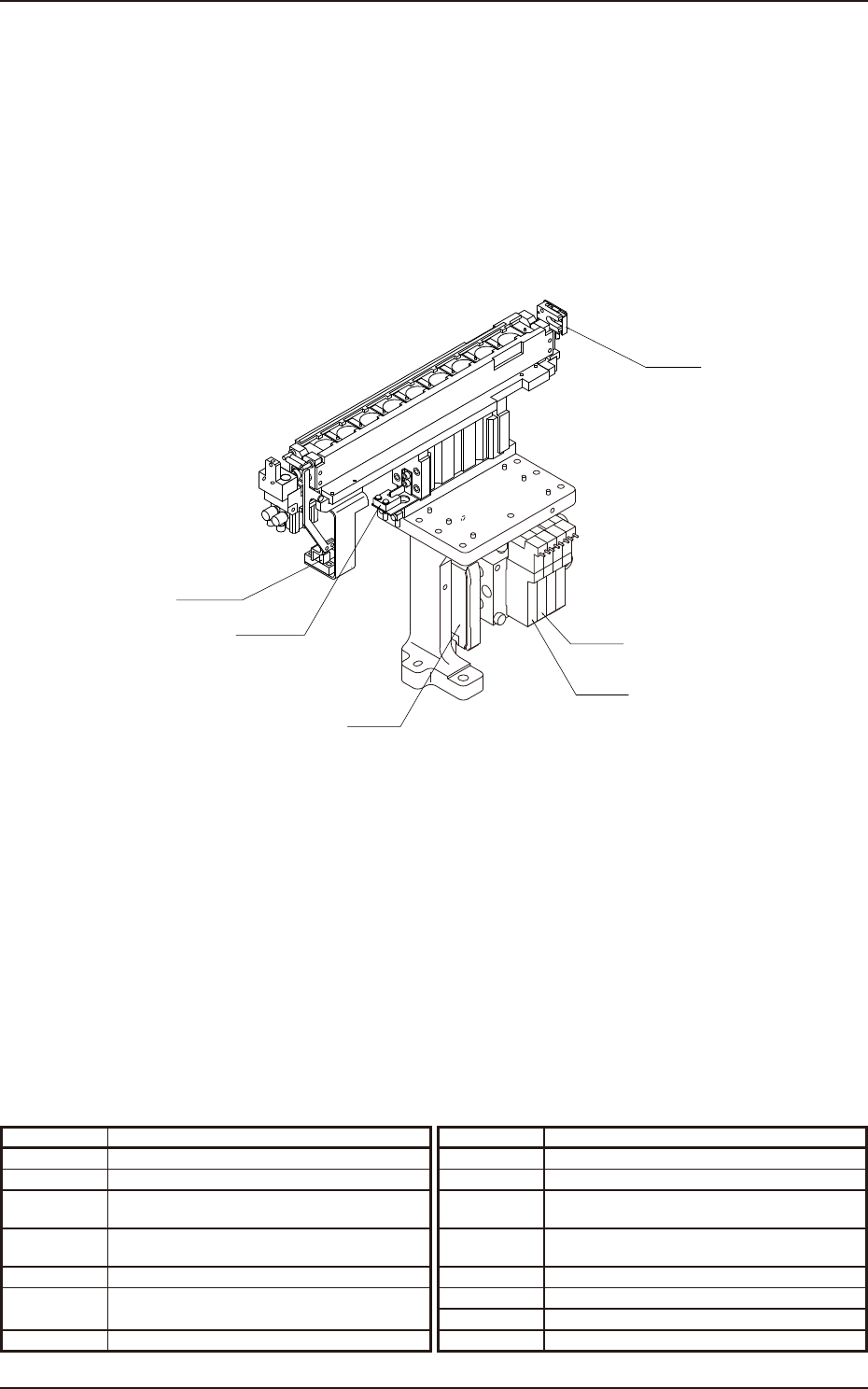
1.20 Nozzle Stocker for Multi-Functional Nozzle Section Layout
B_DWN1
B_SH1
Y_UP1
Y_SH
B_CMP1
B1611
Symbol Name Symbol Name
Y_SH Nozzle Stocker 2 Shutter Open/Close 1
Y_UP1 Multi Function Nozzle Stocker 2 Ascending 1
B_DWN1 Multi Function Nozzle Stocker 2
Unit Lower Limit Detection 1
B_SH1 Multi Function Nozzle Stocker 2
Shutter Close Check 1
B_CMP1
Multi Function Nozzle Stocker 2 Clamp Check 1
B_1611
Multi Function Nozzle Stocker 2
Setup Error Detection
1.20 Nozzle Stocker for Multi-Functional Nozzle Section Layout

199-5100
Chapter 3
Parts Location
This chapter describes the layout, etc., of each section.
As this contains highly sophisticated contents, it should carefully
be referred to.
1. Parts Location
EUKYX
EUKYX
3-1199-5100
1. Parts Location
1. Parts Location
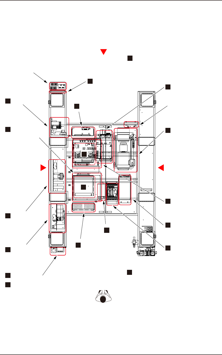
1.1 Layout under the Base (General View)
Q221
INPUT : 100-240VA 0.5 A 50/60Hz
HWS15 - 5 /A
OUTPUT : 5 V 3 A
R
1
2
7
8
IC1
L
E
D
8
(赤)
L
E
D
7
L
E
D
6
L
E
D
5
L
E
D
4
L
E
D
3
L
E
D
2
L
E
D
1
1
2
7
8
1
2
13
14
1
2
9
10
1
2
9
10
1
2
9
10
1
2
9
10
1
2
23
24
1
2
5
6
1
2
15
16
1
2
13
14
1
2
15
16
1
2
9
10
1
2
9
10
1
2
9
10
1
2
9
10
1
2
19
20
X1
1
2
3
4
1
2
3
4
1
2
9
10
1
2
9
10
1
2
25
26
1
2
25
26
1
2
25
26
1
2
25
26
SW1
12 3 45 67 8
ON
1 6
3
4
1 6
3
4
1 6
3
4
1 6
3
4
1 6
3
4
1 6
3
4
X2
61
1
2
7
8
1
2
7
8
1
2
7
8
CN1
1
2
7
8
1
2
7
8
1
2
3
4
1
2
3
4
1
2
3
4
1
2
3
4
1
2
9
10
1
2
9
10
1
2
9
10
1
2
9
10
CN2 CN3 CN4 CN5 CN6 CN7
CN8 CN9
CN60
CN10
1
2
29
30
1
2
29
30
1
2
21
22
omron
1 8
3
4
6
5
1 6
3
4
1 6
3
4
CN11 CN12 CN13 CN14
CN15 CN16
CN17 CN18
CN20CN19
CN22CN21
CN23
CN24
CN25
CN26 CN27
CN28
CN29
CN31
CN30
CN32
CN36CN35CN34CN33
CN37 CN38 CN39 CN40
CN42CN41
CN43 CN44
CN51
CN45 CN46
CN53 CN54
CN47 CN48
CN55 CN56
CN49 CN50
CN57 CN58
INPUT(A)OUTPUT(A)
DUAL-A DUAL-A
INPUT(B)OUTPUT(B)
SINGLE/DUAL-B SINGLE/DUAL-B
LED Lighting Control PCB
SIDE A
XY Motor
Amplifier Unit
Front
SIDE B
Head Section
Motor Amplifier Unit
ATX Power
CPU1
CPU2
FRONT
Side Panel Front
Side Panel Center
Side Panel Rear
Head Section
I/O PCB Panel
DC Power
Supply Unit
Vacuum
Pump
Relay PCB
Input and output Interface
Connector Section
REAR
Cooling Fan
I/O PCB
Noise Filter
Power Breaker
XY Motor Amplifier Unit Rear
9
10
10
15
7
7
11
16
6
8
12
17
1
2
3
14
4
13
5