00195170-01 SA trailing cable.pdf - 第24页
Replacing the Trailing Cable Unit (IGUS) on X- Series Machines from B-079 [03 021065-xx] onwards Overview 24 Service Manual Exchange of the trai ling cable SIPLACE HF and X-Series 4.3 Overview Shortening the Y hoses to t…
Replacing the Trailing Cable Unit (IGUS) on X-Series Machines from B-079
[03021065-xx] onwards
Service Manual Exchange of the trailing cable SIPLACE HF and X-Series
23
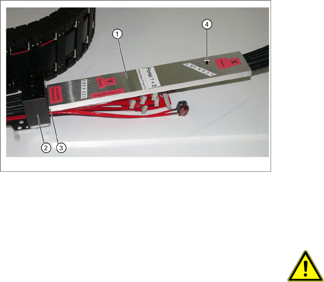
Shorten the X hoses at the X tailing cable
clamp (to the pneumatic distributor at the
head mount)
1. Gauge for shortening the hoses
2. X trailing cable clamp
3. Stop edge (gauge at clamp)
4. Hose markings
X The gauges (1) are labeled for the appropriate
gantries (gantries 1+3 or 2+4). Select the cor-
rect gauge.
X Place the edge (3) of the gauge (see the An-
schlagkante Klemmung X+Y marking on the
gauge) against the edge of the X trailing cable
clamping plate (2).
X Mark the compressed air hoses through the
drillings (4) in the gauge. See the X-Schlauch
marking on the gauge.
ATTENTION:
Mark the correct position!
X See the X-Schlauch marking on the
gauge.
X See the Innenseite Maschine
marking on the gauge.
X The compressed air hoses need to
be cut through at the markings la-
beled as „X-Schlauch“, to ensure
that they are the correct length. If
the hoses are cut too short, the
entire trailing cable will need to be
discarded.
X Use the hose nippers to cut the compressed
air hoses at the points marked. The hoses can
now be inserted into the pneumatic distributor
with the optimum curvature.
Replacing the Trailing Cable Unit (IGUS) on X-Series Machines from B-079 [03021065-xx] onwards
Overview
24 Service Manual Exchange of the trailing cable SIPLACE HF and X-Series
4.3 Overview
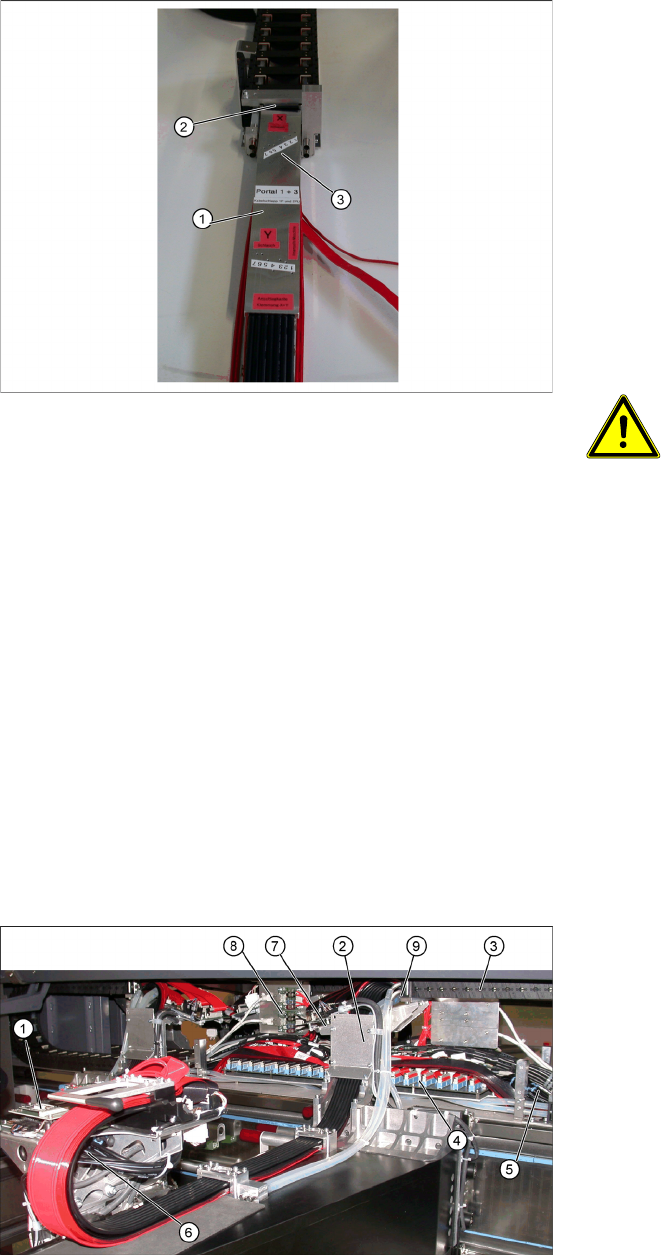
Shortening the Y hoses to the pneumatic
distributor in the machine base
1. Gauge for shortening the hoses
2. Clamp stop edge on the machine base
3. Hose markings
X The gauges (1) are labeled for the appropriate
gantries (gantries 1+3 or 2+4). Select the cor-
rect gauge.
X Place the edge (2) of the gauge (see the An-
schlagkante Klemmung X+Y marking on the
gauge) against the edge of the Y-axis clamp.
X Mark the compressed air hoses through the
drillings (3) in the gauge.
ATTENTION:
Mark the correct position!
X See the Y-Schlauch marking on
the gauge.
X The compressed air hoses need to
be cut through at the markings la-
beled as „Y-Schlauch“, to ensure
that they are the correct length. If
the hoses are cut too short, the
entire trailing cable will need to be
discarded.
X Use the hose nippers to cut the compressed
air hoses at the points marked. The hoses can
now be connected to the separated compres-
sed air hoses in the machine base, with the op-
timum length.
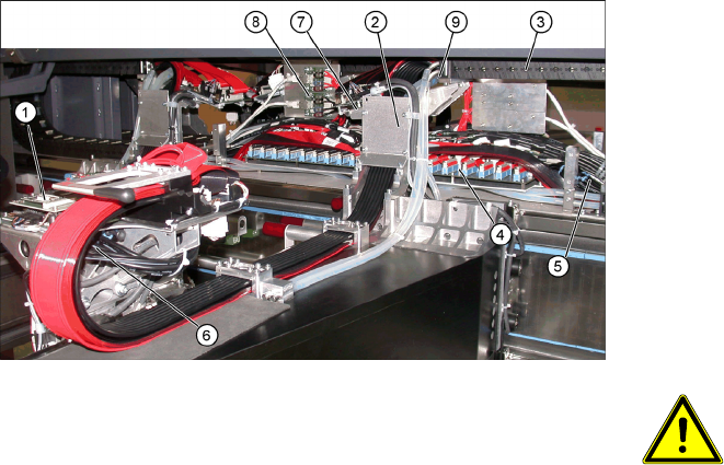
1. Head board
2. Trailing cable console
3. Power track chain
4. Trailing cable interface
5. Compressed air hoses to the pneumatic distri-
butor (in the machine base)
6. Gantry distributor
7. Gantry interface
8. Hotlink card
9. Connection piece for cooling tubes to Y-axis
motor
Replacing the Trailing Cable Unit (IGUS) on X-Series Machines from B-079
[03021065-xx] onwards
Service Manual Exchange of the trailing cable SIPLACE HF and X-Series
25
See also:
J 4.2 Preparing the Trailing Cable Unit [J 22]
J 1.3 Handling the Hose Unlocking Device [03047090-xx] [J 6]
X The flat ribbon cable and the camera cable are
run from the head board (1), via the trailing ca-
ble console(2) and the power track chain (3) to
the gantry interface (7) and trailing cable inter-
face (4). The camera cable ends at the hotlink
card (8).
X The compressed air hoses are run from the
pneumatic distributor (6), via the trailing cable
console (2) and the power track chain(3) to the
gantry distributor in the machine base .
X Disconnect the camera cable from the hotlink
card (8).
X Remove cable ties where necessary.
ATTENTION:
Observe the order in which the con-
nections are arranged.
X Label the plug-in connections to the
flat ribbon cables and the camera
cable for subsequent reinstallation.
X Pull the cooling tubesfor the Y motor off the
connection piece.(9).