00195170-01 SA trailing cable.pdf - 第25页
Replacing the Trailing Cable Unit (IGU S) on X-Series Machines from B-079 [03021065-xx] onwards Service Manual Exchange of the trailing cable SIPLACE HF and X-Series 25 See also: J 4.2 Preparing the Trailing Cable Unit […
Replacing the Trailing Cable Unit (IGUS) on X-Series Machines from B-079 [03021065-xx] onwards
Overview
24 Service Manual Exchange of the trailing cable SIPLACE HF and X-Series
4.3 Overview
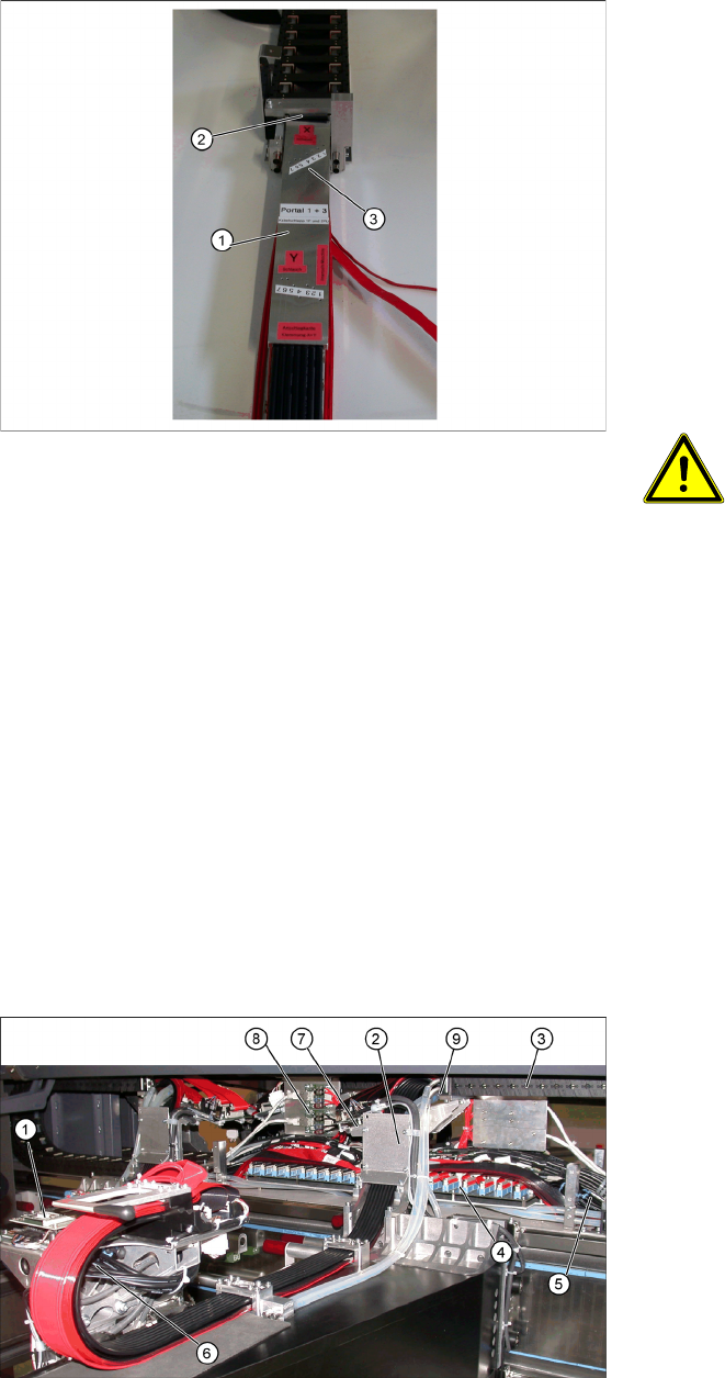
Shortening the Y hoses to the pneumatic
distributor in the machine base
1. Gauge for shortening the hoses
2. Clamp stop edge on the machine base
3. Hose markings
X The gauges (1) are labeled for the appropriate
gantries (gantries 1+3 or 2+4). Select the cor-
rect gauge.
X Place the edge (2) of the gauge (see the An-
schlagkante Klemmung X+Y marking on the
gauge) against the edge of the Y-axis clamp.
X Mark the compressed air hoses through the
drillings (3) in the gauge.
ATTENTION:
Mark the correct position!
X See the Y-Schlauch marking on
the gauge.
X The compressed air hoses need to
be cut through at the markings la-
beled as „Y-Schlauch“, to ensure
that they are the correct length. If
the hoses are cut too short, the
entire trailing cable will need to be
discarded.
X Use the hose nippers to cut the compressed
air hoses at the points marked. The hoses can
now be connected to the separated compres-
sed air hoses in the machine base, with the op-
timum length.
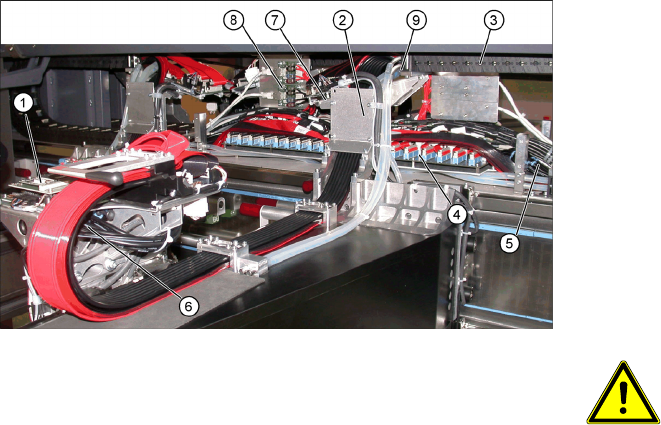
1. Head board
2. Trailing cable console
3. Power track chain
4. Trailing cable interface
5. Compressed air hoses to the pneumatic distri-
butor (in the machine base)
6. Gantry distributor
7. Gantry interface
8. Hotlink card
9. Connection piece for cooling tubes to Y-axis
motor
Replacing the Trailing Cable Unit (IGUS) on X-Series Machines from B-079
[03021065-xx] onwards
Service Manual Exchange of the trailing cable SIPLACE HF and X-Series
25
See also:
J 4.2 Preparing the Trailing Cable Unit [J 22]
J 1.3 Handling the Hose Unlocking Device [03047090-xx] [J 6]
X The flat ribbon cable and the camera cable are
run from the head board (1), via the trailing ca-
ble console(2) and the power track chain (3) to
the gantry interface (7) and trailing cable inter-
face (4). The camera cable ends at the hotlink
card (8).
X The compressed air hoses are run from the
pneumatic distributor (6), via the trailing cable
console (2) and the power track chain(3) to the
gantry distributor in the machine base .
X Disconnect the camera cable from the hotlink
card (8).
X Remove cable ties where necessary.
ATTENTION:
Observe the order in which the con-
nections are arranged.
X Label the plug-in connections to the
flat ribbon cables and the camera
cable for subsequent reinstallation.
X Pull the cooling tubesfor the Y motor off the
connection piece.(9).
Replacing the Trailing Cable Unit (IGUS) on X-Series Machines from B-079 [03021065-xx] onwards
Disassembly
26 Service Manual Exchange of the trailing cable SIPLACE HF and X-Series
4.4 Disassembly
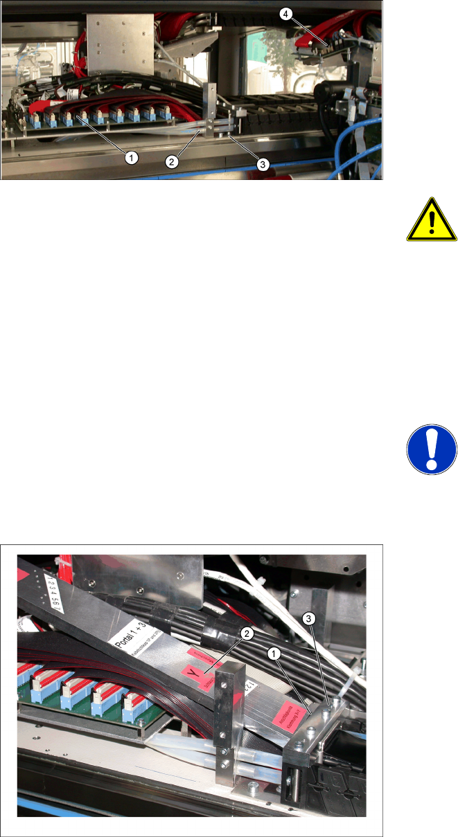
1. Trailing cable interface
2. Pneumatics for vacuum pump (option)
3. Mounting block for trailing cable
4. Gantry interface
X Disconnect the flat ribbon cable at the trailing
cable interface (1). Take care not to lose the
brackets for the plug-and-socket connections.
They could fall out and be lost.
X Remove cable ties where necessary.
ATTENTION:
Observe the order in which the con-
nections are arranged.
X Label the plug-in connections to the
flat ribbon cables for subsequent
reinstallation.
X Remove all necessary cable ties from the gan-
try interface (4) and unplug the flat ribbon ca-
ble.
X Disconnect the cables for the motor, proximity
switches, read head and temperature sensor
from the gantry interface (4) .
NOTE: Dismantle the gantry inter-
face board
The gantry interface board is fitted
onto the holder of the new trailing ca-
ble unit.
Proceed as follows to cut the compressed air ho-
ses which lead to the pneumatic distributor inside
the machine base:
X Place the gauge (1) against the mounting
block (3).
X Use the gauge to label the hoses at the mar-
king Y-Schlauch (2).