Preventive_Maintenance.pdf - 第12页
Preventive Maintenance - XPM 2 12 Revision Date: October 2004 Procedure 9: Check and Clean Sample Ports (Interval - 3 months) If the Oven is equipped with the Optional Integrated Oxygen Analyzer the sample ports must be …
Preventive Maintenance - XPM
2
11 Revision Date: October 2004
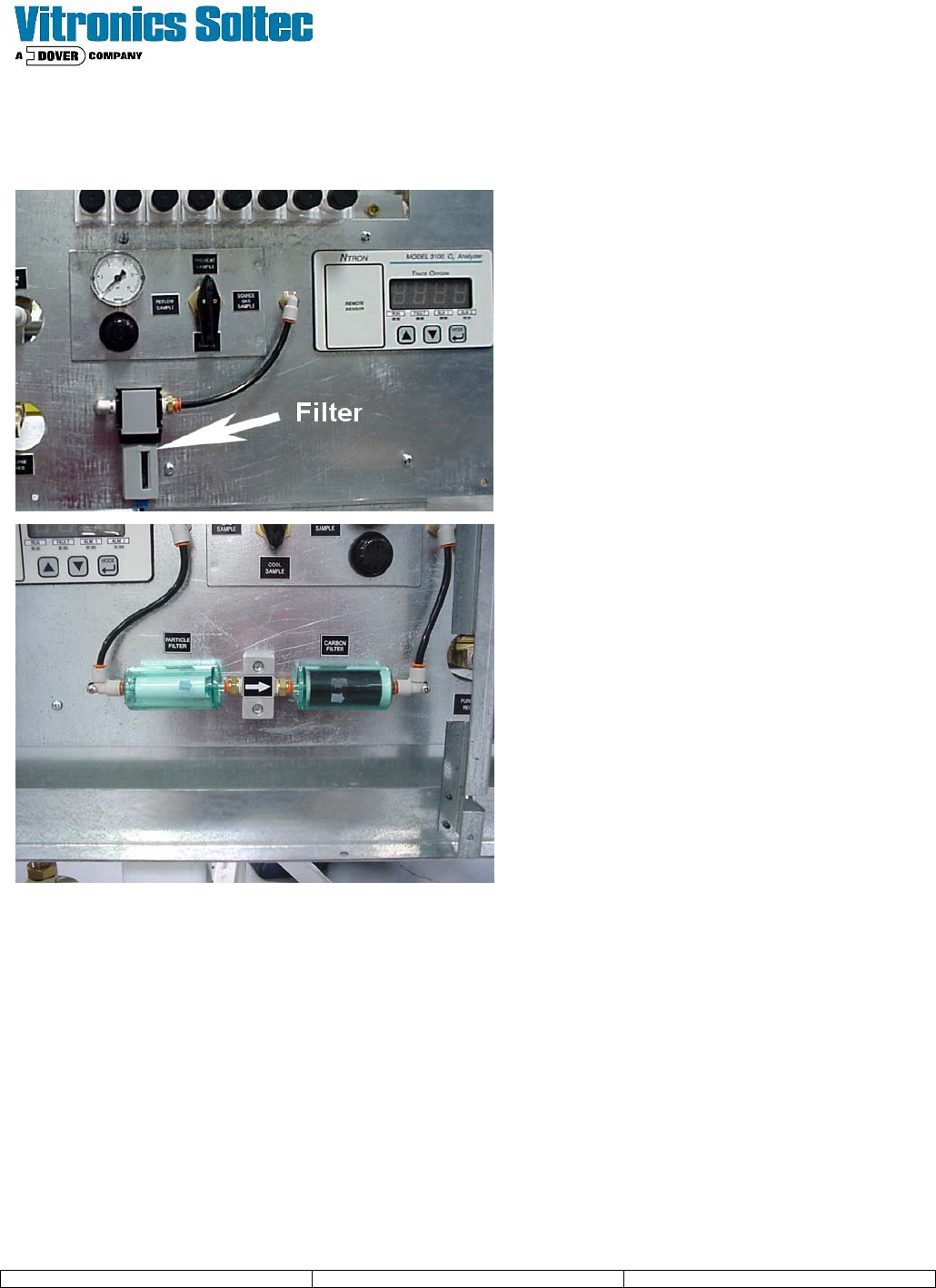
Procedure 8: Check and Replace In-line Filters on Optional Oxygen Analyzer
(Interval - 3 months)
If the Oven is equipped with the Optional
Integrated Oxygen Analyzer, the in-line filter must
be clean in order to operate properly. This filter is
located in line with the analyzer on the pneumatics
panel.
(your panel may be a mirror image of the pictures
shown depending on machine configuration)
Preventive Maintenance - XPM
2
12 Revision Date: October 2004
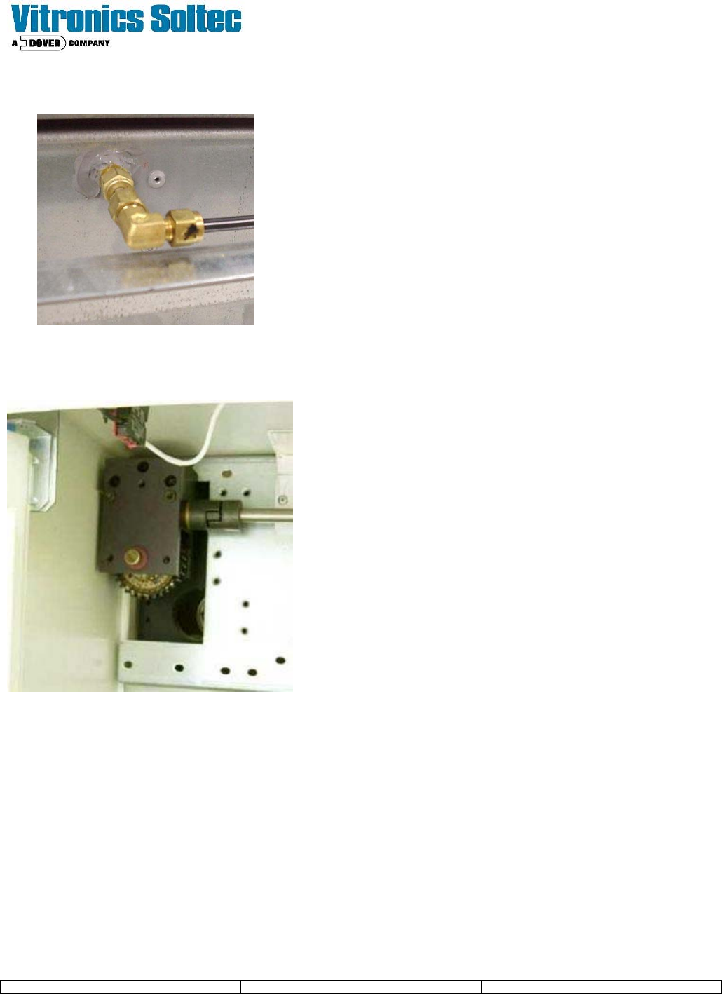
Procedure 9: Check and Clean Sample Ports
(Interval - 3 months)
If the Oven is equipped with the Optional Integrated Oxygen
Analyzer the sample ports must be also be checked and cleaned.
Depending on the oven usage and materials used in the process
there may be residue which could plug the fitting.
Loosen and remove the connection fitting to the black tubing.
Disassemble the right angle fitting and clean the insides of all
parts of the feed through with a small brush and Isopropyl Alcohol.
Reassemble and use care not to over-tighten and damage the
fitting
Procedure 10: Clean and lubricate all Rail Width Adjust Worms and Gears.
(Interval - 6 months)
Remove all front sheet metal covers to expose the all of the rail
width adjust worm gear assemblies. Apply Amsoil Lithium
Complex Multi Purpose grease or equivalent to the gears.
Raffle
Preventive Maintenance - XPM
2
13 Revision Date: October 2004
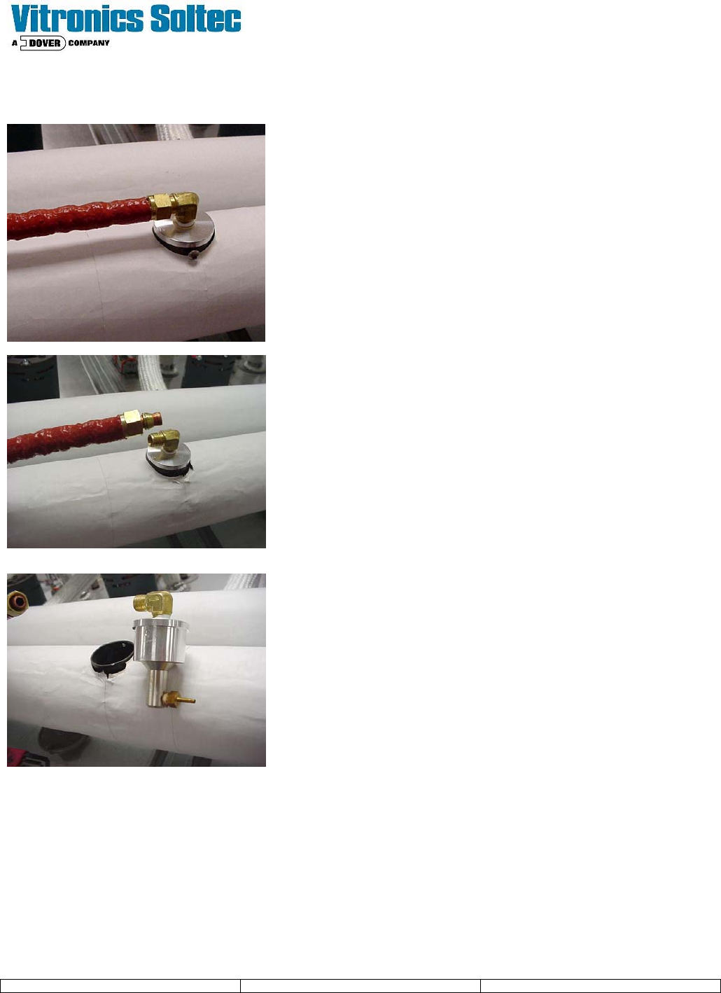
Procedure 11: Inspect and Clean Controlled Exhaust Nozzle
(Interval - 6 months)
Remove the Sheet Metal to access the oven exhaust
system.
The controlled exhaust nozzle is located on the
exhaust piping as shown.
Loosen the fitting at the connection and gently pull the
pipe clear of the fitting.
Note: The pipe is copper tubing and may be stiff to
remove, use care when pulling the pipe loose not to
kink or sharply bend the tubing.
Once the tubing is clear of the nozzle assembly, loosen
the set screw which holds the nozzle in the exhaust
tube.
Gently twist and pull the nozzle assembly to free it from
the
exhaust tube.
Check the injector nozzle to ensure that it is free of
debris.
Clean with Isopropyl Alcohol or equivalent.
Reverse the process to re-assemble Controlled
Exhaust
Nozzle