00193903-02.pdf - 第17页
SIPLACE HF-series / D3 8 External power supply for SIPLACE HF-Series / D3 component trolley 06/2006 Edition 17 1.2 Overview The external power supply is used to power a SIPLACE HF-series component tr olley indepen- dentl…
8 External power supply for SIPLACE HF-Series / D3 component trolley SIPLACE HF-series / D3
06/2006 Edition
16
1.1 Safety instructions
DANGER
Make sure that no one is working on the connected component trolley when you switch on the
power supply.
The external power supply may only be connected to the component trolley if it has been fully dok-
ked out of the placement machine and all electrical connections to the placement machine have
been disconnected.
The device must only be used for its intended purpose, the supply of the component trolley of
SIPLACE HF-series!
The device must not be opened and manipulated.
Before opening the device remove the power plug form the power outlet!
1
1.1.1 Definitions
DANGER
as used in this manual means that death, severe injury or considerable damage to equipment
w i l l occur if the danger instructions are not followed. 1
1
1
1
1
SIPLACE HF-series / D3 8 External power supply for SIPLACE HF-Series / D3 component trolley
06/2006 Edition
17
1.2 Overview
The external power supply is used to power a SIPLACE HF-series component trolley indepen-
dently of the placement machine. 1
The unit is suitable for mains voltages ranging from 88 to 264 V AC. 1
1
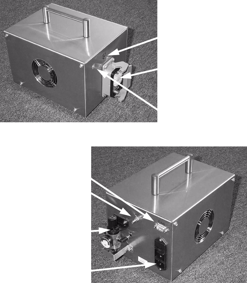
Fig. 2 External power supply for component trolley HF03009868-02 (basic unit)
2
Fig. 3 External power supply for component trolley HF03009868-02 (basic unit)
Multi-function plug for
component trolley
48 V pilot lamp
Location switch
Combination
main power connector
CAN bus connector
Compressed air
connector
Pneumatic unit
8 External power supply for SIPLACE HF-Series / D3 component trolley SIPLACE HF-series / D3
06/2006 Edition
18
3.1 Structure / settings
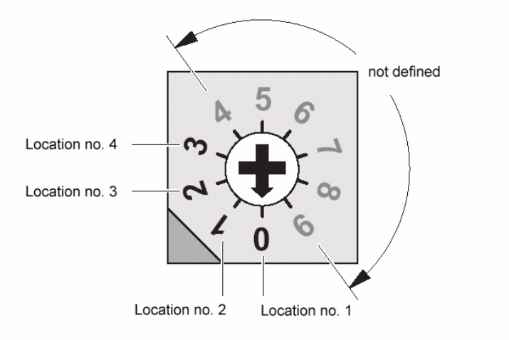
3.1.1 Setting the location number
If several (up to 4) power supplies are connected to a CAN bus, the location number (see figure
below) must be set. 3
Zero corresponds to component feeder table location no. 1 ... three to the fourth, etc. The higher
numbers are not defined. 3
3
Fig. 4 Location number switch (front panel)
4
Zero was set at the factory, i.e. location no. 1. 4
4.0.1 CAN bus
The plug-in CAN bus connector is located on the back of the unit (Fig. 3). 4
It is used to transfer data from a computer. 4
The unit can also be operated as a power supply only (if the CAN bus is not connected). 4
4
4