00193903-02.pdf - 第18页
8 External power supply for SIPLACE HF-Series / D3 component trolley SIPLACE HF-series / D3 06/2006 Edition 18 3.1 S tructure / settings 3.1.1 Setting the location number If several (up to 4) power supplies ar e connecte…
SIPLACE HF-series / D3 8 External power supply for SIPLACE HF-Series / D3 component trolley
06/2006 Edition
17
1.2 Overview
The external power supply is used to power a SIPLACE HF-series component trolley indepen-
dently of the placement machine. 1
The unit is suitable for mains voltages ranging from 88 to 264 V AC. 1
1
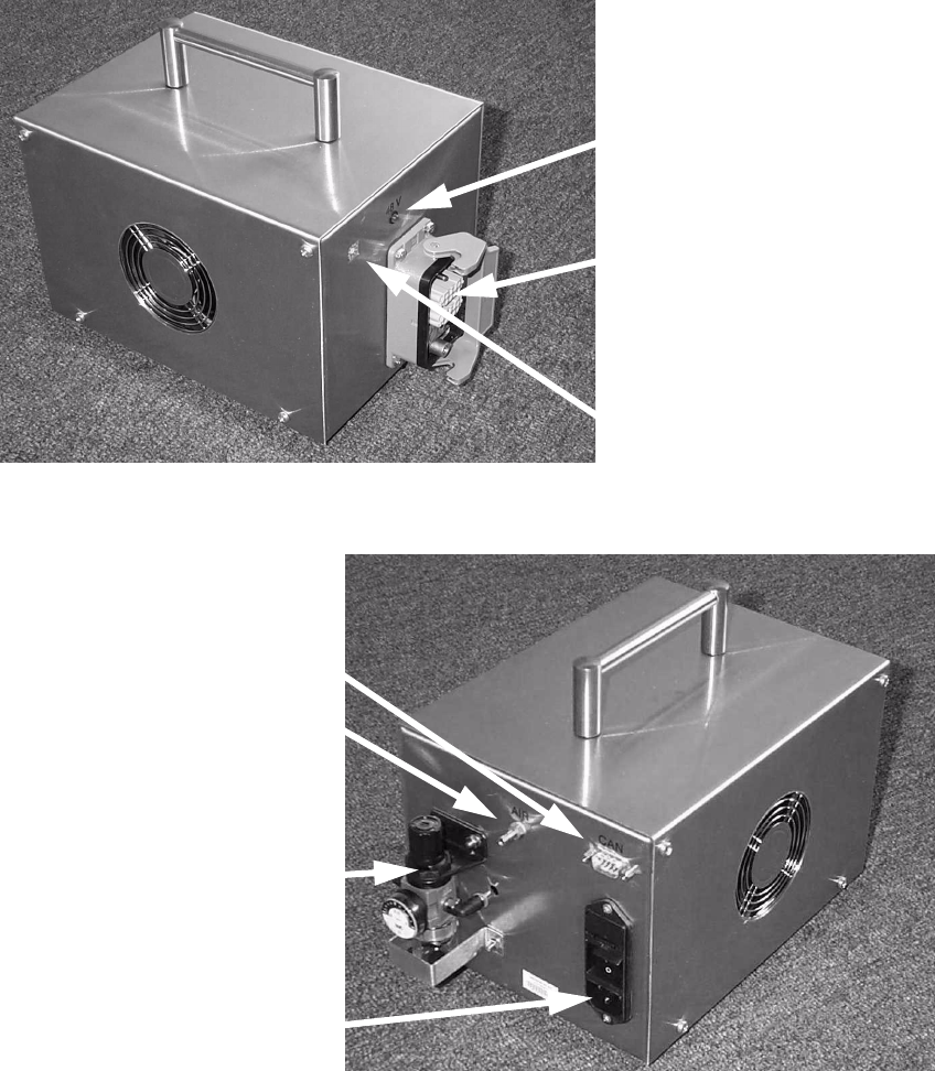
Fig. 2 External power supply for component trolley HF03009868-02 (basic unit)
2
Fig. 3 External power supply for component trolley HF03009868-02 (basic unit)
Multi-function plug for
component trolley
48 V pilot lamp
Location switch
Combination
main power connector
CAN bus connector
Compressed air
connector
Pneumatic unit
8 External power supply for SIPLACE HF-Series / D3 component trolley SIPLACE HF-series / D3
06/2006 Edition
18
3.1 Structure / settings
3.1.1 Setting the location number
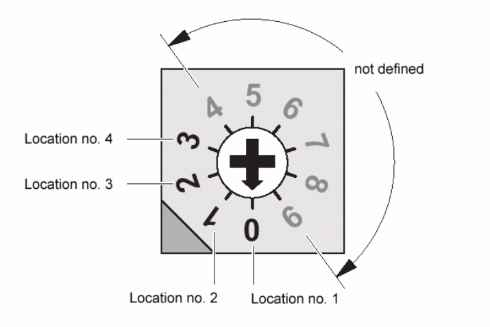
If several (up to 4) power supplies are connected to a CAN bus, the location number (see figure
below) must be set. 3
Zero corresponds to component feeder table location no. 1 ... three to the fourth, etc. The higher
numbers are not defined. 3
3
Fig. 4 Location number switch (front panel)
4
Zero was set at the factory, i.e. location no. 1. 4
4.0.1 CAN bus
The plug-in CAN bus connector is located on the back of the unit (Fig. 3). 4
It is used to transfer data from a computer. 4
The unit can also be operated as a power supply only (if the CAN bus is not connected). 4
4
4
SIPLACE HF-series / D3 8 External power supply for SIPLACE HF-Series / D3 component trolley
06/2006 Edition
19
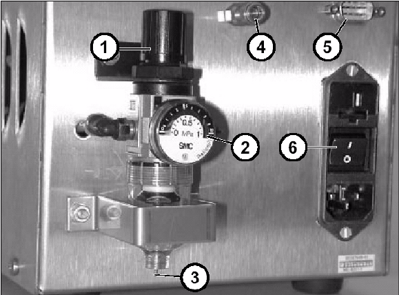
4.0.2 Pneumatic unit
This consists of a pressure-reducing valve, manometer and filter with condensate tank. 4
The manometer displays the output pressure, which can be set by lifting up and turning the cap
(1). 4
4
Fig. 5 Back panel with pneumatic unit, etc.
5
a Cap of pressure-reducing valve
s Manometer
d Manual drain valve
f Compressed air connector
g CAN bus connector
h Power switch