00193903-02.pdf - 第19页
SIPLACE HF-series / D3 8 External power supply for SIPLACE HF-Series / D3 component trolley 06/2006 Edition 19 4.0.2 Pneumatic unit This consists of a pressure -reducing valve , manometer and filter with condensate t ank…
8 External power supply for SIPLACE HF-Series / D3 component trolley SIPLACE HF-series / D3
06/2006 Edition
18
3.1 Structure / settings
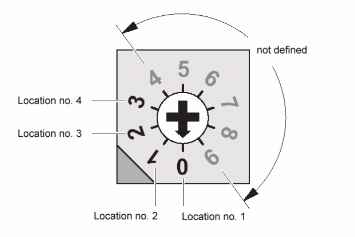
3.1.1 Setting the location number
If several (up to 4) power supplies are connected to a CAN bus, the location number (see figure
below) must be set. 3
Zero corresponds to component feeder table location no. 1 ... three to the fourth, etc. The higher
numbers are not defined. 3
3
Fig. 4 Location number switch (front panel)
4
Zero was set at the factory, i.e. location no. 1. 4
4.0.1 CAN bus
The plug-in CAN bus connector is located on the back of the unit (Fig. 3). 4
It is used to transfer data from a computer. 4
The unit can also be operated as a power supply only (if the CAN bus is not connected). 4
4
4
SIPLACE HF-series / D3 8 External power supply for SIPLACE HF-Series / D3 component trolley
06/2006 Edition
19
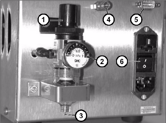
4.0.2 Pneumatic unit
This consists of a pressure-reducing valve, manometer and filter with condensate tank. 4
The manometer displays the output pressure, which can be set by lifting up and turning the cap
(1). 4
4
Fig. 5 Back panel with pneumatic unit, etc.
5
a Cap of pressure-reducing valve
s Manometer
d Manual drain valve
f Compressed air connector
g CAN bus connector
h Power switch
8 External power supply for SIPLACE HF-Series / D3 component trolley SIPLACE HF-series / D3
06/2006 Edition
20
5.1 Commissioning
: Use the enclosed power cable (03006765-01) to connect the component trolley to the external
power supply.
: Then lock both the multi-function plug on the power supply and the connector on the compo-
nent trolley with the relevant locking clips.
DANGER
The air outlet opening of the integral fan and the ventilation slots on the side of the unit must not
be covered.
This could cause overheating, which would damage the power supply. 5
: Optional: Plug the cable into the CAN bus connector (Fig. 3).
: If this has not already been done, fix the quick-release coupling correctly to the compressed
air hose.
: Connect the compressed air hose to the compressed air connector (Fig. 3).
: First switch off the power switch (Fig. 3) and then plug the power cable into the unit.
DANGER
Make sure that no one is working on the connected component table when you switch on the po-
wer supply. 5
: Switch on at the power switch (Fig. 3).
: There is a pilot lamp on the front panel (Fig. 2). The power supply is only guaranteed when this
lamp lights up.
: Lift the cap of the pressure-reducing valve (Fig. 5 and turn it until the manometer (Fig. 5) reads
250 kPa (turn clockwise to increase the pressure).