SA_HF_intern_0194307-02_eng.pdf - 第65页
SIPL ACE HF-Ser ies Replacing the Cu tter Blades [03009259 - xx] Serv ice Cu tter 3 Copy ri ght © 200 4 S ie m ens 0019 43 07- 02 Is su e 1 1/ 2004 3-51 Final Work 1 2 Use a feeler gauge to check the gap betw een the t…
3
Service
Cutter
SIPLACE HF-Series
Replacing the Cutter Blades [03009259-xx]
3-50
00194307-02 Issue 11/2004 Copyright © 2004 Siemens
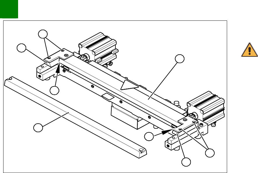
1
2
4
1
5
4
3
2
Lubricate the contact/slide surfaces for the moveable blade, as
described in the section „Preparation“.
CAUTION
Do not lubricate the blades themselves.
Place a shim (0.5 - 1.0 mm thickness) on the left and right,
between the spacer and the front of the blade (1).
Place the previously removed holding-down device (2) onto the
new spacers.
The holding-down devices with function status 03 are
designed for use with cutters of function status -04 (= with
tape deflector).
Reinsert the tape deflector unit (3) and screw in the 4 hexagon
socket-head screws (4) by hand.
Push the spacers (with inserted shim)as far as possible in the
direction of the moveable blade. The maximum permissible gap
is 1.0 mm.
In this position, tighten the 4 screws (4) on the tape deflector
holder crosswise (tightening torque).
Remove the two shims.
Insert the new stationary blade (5) in the correct position and
screw tighten.
SIPLACE HF-Series
Replacing the Cutter Blades [03009259-xx]
Service
Cutter
3
Copyright © 2004 Siemens 00194307-02 Issue 11/2004 3-51
Final Work
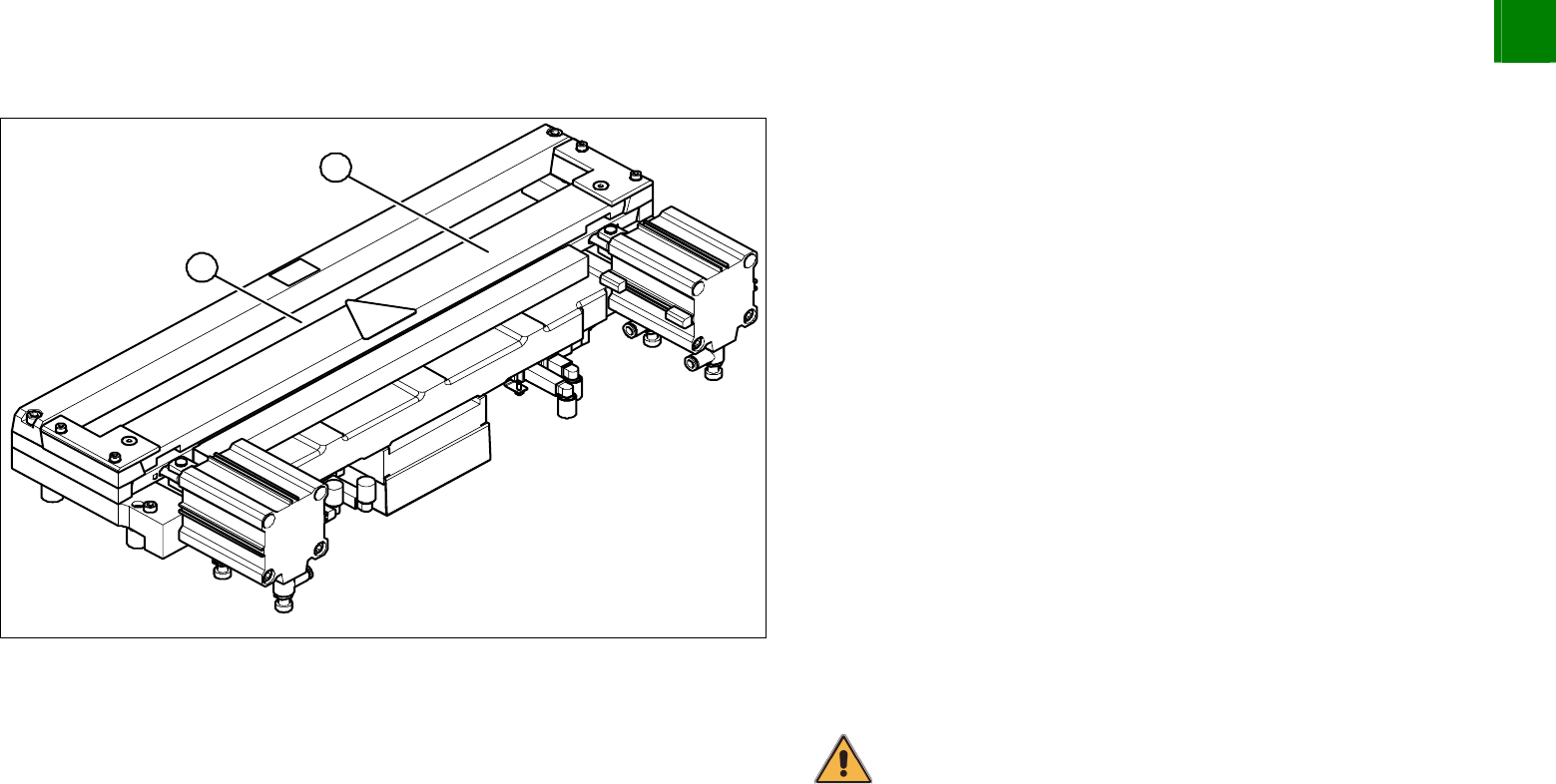
1
2
Use a feeler gauge to check the gap between the tape deflector
(1) and the moveable blade (2), along the entire length and
width of the blade.
The 0.05 mm feeler gauge should fit through the gap.
The 0.25 mm feeler gauge should not fit through the gap.
If the gap is not correct, check:
Whether the wrong holding-down device has been installed
(with function status < 03)
The holding-down devices are those designed for cutters
with function status -04 (= with tape deflector)
Whether the blades, tape deflector etc. were cleaned
before installation
If the gap is correct:
Replace the protective sheet, deflector plate and cover plate.
Make sure that the edges are parallel.
CAUTION
Make sure that the cables and hoses are not trapped or subjected to
excess strain.
Remove the clamps form the cutter/ remove the cutter from the
assembly plate.
Install the cutter.
3
Service
Modular PCB Conveyor System
SIPLACE HF-Series
Replacing the Toothed Belt for the Width Adjustment System Drive [00369662-xx]
3-52
00194307-02 Issue 11/2004 Copyright © 2004 Siemens
3.3 Modular PCB Conveyor System
3.3.1 Replacing the Toothed Belt for the Width Adjustment System Drive [00369662-xx]
Tools
3 small or medium screw clamps
Overview
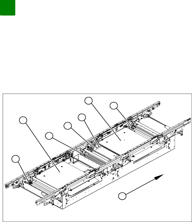
1
1
2
4
4
1
5
3
1. Adjustment units 1,2 and 3 with ball screws
2. Stepping motor for width adjustment system
3. Toothed belt for the drive
4. Lifting table plates BB1 and BB2
5. Direction of transport
Move the conveyor system to minimum width.
Undo the screws fastening the lifting table plates and remove
the lifting table plates from the lifting table unit.