00195044-16_UM_VisionTeachStation_DE_EN.pdf - 第176页
11 Measuring components Vision Teach Station User Manual 11.1 Preparing components for the measurement 05/2016 Edition 176 PLEASE NOTE: 11 It is very important to accurately set the distance between the component and the…

Vision Teach Station User Manual 11 Measuring components
05/2016 Edition 11.1 Preparing components for the measurement
175
11 Measuring components
11.1 Preparing components for the measurement
11.1.1 Placing the component on the component support
Release the lock on the positioning unit (item 2 in Fig. 11.1 - 1, page 177) using the magnetic
switch (item 2 in Fig. 11.1 - 1, page 177).
Push the positioning unit (item 2 in Fig. 11.1 - 1, page 177) outwards out of the range of the
component camera (item 7 in Fig. 11.1 - 1, page 177).
On the component support (item 5 in Fig. 11.1 - 1, page 177), the center point is identified by
a mark (item 6 in Fig. 11.1 - 1, page 177).
Place the component on the component support so that the middle of the component tallies
with the center point of the component support (item 6 11.1 - 1, page 177).
Place components with leads or balls on their backs. The leads or balls should point up to the
camera.
Only use double-sided adhesive tape between the support and component to secure the com-
ponent and prevent it slipping if absolutely essential.
Make sure that the white adhesive tape does not project over the body of the component. This
could corrupt the measurement.
Turn the component support so that the edges of the component are parallel to the camera
edges.
Make sure that the coordinate systems are aligned correctly (see chapter 12, page 182).
Push the positioning unit until the middle of the component is roughly under the camera.
Hold the focus point adjusting guide against the bottom edge of the camera.
Turn the adjusting ring (item 4 in Fig. 11.1 - 1, page 177) up until the component just stops
touching the adjusting guide.
Carefully pull the positioning unit back and remove the adjusting guide (see Fig. 11.1 - 2, page
178).
Be careful not to damage the component.
PLEASE NOTE: 11
The focus point must be set with an accuracy < ± 0.4 mm, otherwise the component will be
mapped too large or too small.
Each camera has its own adjustment guide for the focus point (see section 3.2, from page
106). The focus distances are listed in section 13, page 184. 11

11 Measuring components Vision Teach Station User Manual
11.1 Preparing components for the measurement 05/2016 Edition
176
PLEASE NOTE: 11
It is very important to accurately set the distance between the component and the camera,
otherwise the component cannot be mapped correctly on the camera, i.e. the shape of the
image will not correspond exactly to the shape of the component. If the distance is wrong, the
component will appear too large or too small. The geometric description will not tally with the
actual component. 11
Vision Teach Station User Manual 11 Measuring components
05/2016 Edition 11.1 Preparing components for the measurement
177
11
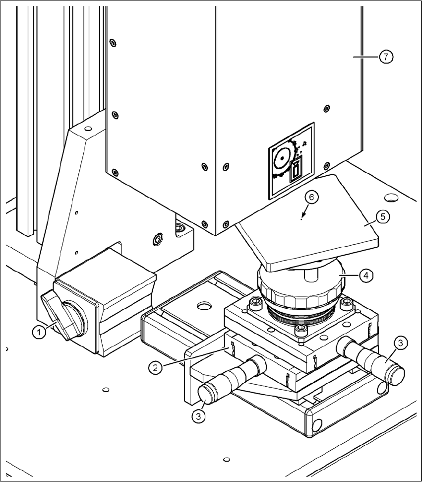
Fig. 11.1 - 1 Base module - Placing the component on the component support
(1) Magnetic switch
(2) Positioning unit
(3) Micrometer screw for positioning the component support
(4) Adjusting ring for adjusting the height of the component support
(5) Component support, rotating, for optimum angular alignment during the measurement
(6) Centering fiducial on the component support
(7) Component camera